VW Polo manuals

Volkswagen Polo Service & Repair Manual: General Information

Vehicles with a high voltage system (hybrid vehicles)
Observe all of the additional warnings for all work performed on vehicles with the high voltage system. Refer to → Electrical Equipment; Rep. Gr.93.
  WARNING
Risk of unintended engine start
The ignition must be turned off and the ignition key must remain outside of the vehicle when working on vehicles with a high voltage system.
  WARNING
Handling high voltage cables:
Do not stand on or place tools on high voltage cables and their components as it may damage the cable insulation.
Never bend or kink high voltage cables forcefully as it may damage the cable insulation.
The round high voltage connectors are color coded with an external color ring and are mechanically coded using the guide- or code tabs. Always make certain that the coding matches when connecting the round connector in order to avoid any mechanical damage the high voltage connector.
  DANGER!
There is a risk of electrocution from damaged high voltage components.
Observe the following when working around high voltage components and high voltage wires:
Never work around high voltage components and cables with cutting, deformed, or sharp edged tools, or heat sources such as welding or soldering tools, heated air, and thermal glue.
Inspect the high voltage components visually before beginning.
Perform a visual inspection of the Electric Drive Power and Control Electronics -JX1-, the Electro-Drive Drive Motor -V141-, the Electrical A/C Compressor -V470- and the high voltage lines when working in the engine compartment.
Perform a visual inspection of the high voltage lines and covers when working on the underbody.
Perform a visual inspection of the high voltage lines and the Electrobox with the High Voltage System Maintenance Connector -TW- when working in the luggage compartment.
Perform a visual inspection on all of the potential equalization cables.
Observe the following items when performing the visual inspection:
The components do not display any signs of external damage.
The high voltage cable insulation and the potential equalization cables are not damaged.
The high voltage cables do not display any abnormal deformations.
Every high voltage component is marked with a red warning label.
If it is necessary to perform work in the vicinity of high voltage components, perform a “visual inspection” of the high voltage components and cables for damage and follow the “general warnings when working on the high voltage system”. Refer to → Electrical Equipment; Rep. Gr.93.
If it is necessary to perform work on the high voltage components, disable the high voltage system. Refer to → Electrical Equipment; Rep. Gr.93 and read and follow the “high voltage electrical system general warnings” → Electrical Equipment; Rep. Gr.93.
  Caution
If it is suspected that chemicals were added to the refrigerant circuit to seal leaks, do not connect the A/C service station and do not extract the refrigerant.
Chemicals that seal leaks in the coolant circuit form deposits that affect the function of the A/C system and lead to failure of the A/C system and the A/C service station.
Remind the customer that the refrigerant circuit contains substances that VW has not approved. As such, the refrigerant circuit cannot be flushed. It is only possible to service the refrigerant circuit by replacing all the components which come in contact with this material.
  Note
VW does not approve the use of chemicals to seal leaks in the refrigerant circuit.
Chemicals used to seal leaks in the refrigerant circuit often react with air and the moisture in it. They cause deposits in the refrigerant circuit and the A/C service station and malfunctions in valves and other components that they come in contact with. These deposits cannot be removed completely from the components, even by flushing. It is only possible to service the refrigerant circuit by replacing all the components which come in contact with this material.
Chemicals used to seal leaks in the refrigerant circuit usually cannot be detected from outside. The label that should be applied to identify it is often missing. Therefore be careful when working with if you do not know its service history.
Refrigerant circuit must be flushed with refrigerant R134a in order to force out contaminants (e.g. abraded material from a malfunctioning A/C compressor) as well as old refrigerant oil as efficiently and as cleanly as possible and without the need for extensive work.
For vehicles with an electrically-driven A/C compressor, pay attention to the notes for replacing the Electrical A/C Compressor -V470-. If there is damage on the A/C compressor electronics, the refrigerant circuit must not always be cleaned. Refer to → Chapter „Flushing Not Necessary“.
The refrigerant circuit should be flushed with refrigerant R134a if:
dirt or other contamination is in the refrigerant circuit.
vacuum reading is not maintained on evacuating a leak-free refrigerant circuit (pressure build-up due to moisture in refrigerant circuit).
refrigerant circuit has been left open for longer than normal (e.g. following an accident).
If pressure and temperature measurements in the refrigerant circuit indicate the likelihood of moisture in the circuit.
In the event of doubt about the amount of refrigerant oil in the circuit. If the A/C compressor should be reinstalled, the refrigerant should be drained from the compressor via the oil drain plug. To facilitate this, the ribbed belt pulley or magnetic clutch plate on the A/C compressor should be rotated by hand. After flushing, the entire quantity of refrigerant oil specified by vehicle-specific repair manual should be added to the refrigerant circuit (50 grams directly in the A/C compressor). Note additional oil quantity for systems with a second evaporator.
A/C compressor had to be replaced on account of internal damage (e.g. noise or no output).
stipulated by the vehicle-specific repair manual following replacement of certain components.
Another compressor with different refrigerant oil should be installed.
Tools required
A/C Service Station with Flushing Device -VAS6381- or Air Conditioning Flush Tool -VAS6337-. The auxiliary function “Flush refrigerant circuit” and the refrigerant circuit flushing device required for it are present on these A/C service stations. Refer to Special Tools Catalog.
Refrigerant Circuits Adapter Set 1 -VAS6338/1-. Refer to → Chapter „Adapter for Assembling Flushing Circuit“ and Special Tools Catalog
Refrigerant Circuits Adapter Set 2 -VAS6338/50-. Refer to → Chapter „Adapter for Assembling Flushing Circuit“ and Special Tools Catalog.
  Note
If neither of the two A/C service stations listed above are available for use in the workshop, A/C Service Station with Flushing Device -VAS6336/1- or Air Conditioning Flush Tool -VAS6337/1- (depending on the workshop A/C service station version) (min. 7 kg refrigerant R134a in refrigerant bottle) can also be used to flush the refrigerant circuit. However, the flushing procedure must then be performed manually. Refer to → Anchor.
In vehicles with screw-connections on refrigerant circuit, A/C Adapter Set - Adapter 1 -VAG1785/1- through A/C Adapter Set - Adapter 2 -VAG1785/8- from the Refrigerant Circuits Adapter Set 1 -VAS6338/1- or Refrigerant Circuits Adapter Set 2 -VAS6338/50- may be used. In vehicles with screw-connections on A/C compressor and on accumulator, two of the A/C Adapter Set - Adapters 8 -VAG1785/8- are required.
A Refrigerant Circuits Adapter Set 2 - Adapter 31 -VAS6338/31- with 5/8 -18 UNF connections and large internal diameter can be found in the adapter chests in order to be able to bridge components (it is commercially available).
Preliminary work
–  Discharge refrigerant circuit. Refer to → Chapter „Discharge Refrigerant Circuit with A/C Service Station“.
–  Remove A/C compressor. Refer to Heating, Ventilation & Air Conditioning.
On a vehicle with restrictor and reservoir.
–  Remove restrictor (specific to vehicle) and reconnect refrigerant pipes to each other. Refer to Heating, Ventilation & Air Conditioning.
–  Remove reservoir (specific to vehicle). Refer to Heating, Ventilation & Air Conditioning and connect refrigerant pipes to each other (to do this, use adapter and Refrigerant Circuits Adapter Set 1 - Adapter 31 -VAS6338/31-) from Refrigerant Circuits Adapter Set 1 -VAS6338/1-. Refer to → Chapter „Adapter for Assembling Flushing Circuit“.
  Note
The reservoir could be flushed, but it requires too much refrigerant due to its large volume. When this refrigerant is extracted, the reservoir ices up severely and this prolongs the extraction process significantly.
On a vehicle with expansion valve and receiver/dryer.
–  Remove receiver/dryer. Refer to Heating, Ventilation & Air Conditioning (specific to vehicle, not required for all vehicles) and connect refrigerant pipes to each other (for this, use adapters and Refrigerant Circuits Adapter Set 1 - Adapter 31 -VAS6338/31-). Refer to → Chapter „Adapter for Assembling Flushing Circuit“.
–  Remove expansion valve. Refer to Heating, Ventilation & Air Conditioning (specific to vehicle) and install the adapter for it. Refer to → Chapter „Adapter for Assembling Flushing Circuit“.
  Note
If no suitable adapter for the expansion valve is available in Refrigerant Circuits Adapter Set 1 -VAS6338/1- or Refrigerant Circuits Adapter Set 2 -VAS6338/50-, the remove expansion valve can also be drilled open (the expansion valve must be replaced with a new one).
  Caution
Make sure the sealing surfaces on the expansion valve are not damaged when drilling open.
Otherwise refrigerant leaks out.
  Note
   
Several components are to be removed from expansion valve before drilling open.
Expansion valves are available in different versions. For version -A-, components -B-, -C- and -D- must be removed. Then separate regulating element -E- from component -D-. Then drill open expansion valve in area -F- using a suitable drill (6 mm diameter).
For version -G-, parts -H-, -I- and -K- must be removed and then drill open area -L- using suitable drill (6 mm diameter).
Clean the drilled open expansion valve of residue from the work (shavings).
Install parts -B-, -C- and -D- for version -A- or -H- for version -G-.
  Note
In vehicles with two evaporators, the circuit to the second evaporator must be disconnected from circuit of the first evaporator and must be flushed via a separate work procedure. Refer to Heating, Ventilation & Air Conditioning and → Chapter „Adapter for Assembling Flushing Circuit“.
Drilling open the shut-off valve.
  Note
Two shut-off valves are required for flushing the refrigerant circuit/ If the Refrigerant Circuits Adapter Set - Shut-Off Valve -VAS6338/42- is not available to flush the refrigerant circuit, than a shut-off valve is to be drilled out, for example.
 

General Information

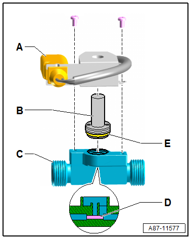
Remove the solenoid coil -A- and the solenoid valve -B- before drilling open.
Drill open the shut-off valve -C- using a suitable drill (diameter of the drill for example 5.0 mm).
Clean the shut-off valve -C- from shavings produced by drilling -D-.
Install the solenoid valve -B- with the seals belonging to it -E- on the drilled open shut-off valve -C-.
Flushing
–  Check refrigerant quantity in the refrigerant cylinder, there must be at least 7 kg of refrigerant R134a.
  Note
If necessary, switch on the heater installed on the refrigerant cylinder for 30 minutes before the first flushing procedure. This increases pressure in the refrigerant cylinder and accelerates charging of the flushing circuit.
–  Evacuate the A/C service station old oil container.
–  Connect the supply hose (high pressure side) of A/C service station to the low pressure line leading to the A/C compressor (line with larger diameter) using an adapter. Refer to → Chapter „Adapter for Assembling Flushing Circuit“.
–  Connect return hose (low pressure- or intake side) of A/C service station to output of refrigerant circuit flushing device.
–  Connect the input on the refrigerant circuit flushing device to the high pressure line leading to the A/C compressor (line with smaller diameter) using an adapter. Refer to → Chapter „Adapter for Assembling Flushing Circuit“.
  Note
Components are always (with the exception of the electrically-driven A/C compressor) flushed in the opposite direction of refrigerant flow when the A/C system is operating. Refer to → Chapter „Flushing Circuit Block Diagrams“.
While flushing, contaminants from the refrigerant circuit enter the refrigerant circuit flushing device and the A/C service station and are absorbed by the filters and dryers installed there. Depending on the contaminant, these components are to be replaced in shorter intervals in line with operating instructions for A/C service station or refrigerant circuit flushing device.
The filter in the refrigerant circuit flushing device depends on the type and degree of contamination in the flushed refrigerant circuit. It should be replaced after 2 flushing cycles, at the most. If a heavily contaminated refrigerant circuit is flushed (the refrigerant oil from the circuit is black and viscous or there are many shavings in the refrigerant circuit), the filter should be replaced after flushing. With a refrigerant circuit heavily contaminated in this way, it is wise to flush the circuit again after changing the filter.
Depending on the type of contamination, dirt (old refrigerant oil and abraded material from A/C compressor) is deposited on the viewing glass(es). Clean viewing glass(es) after flushing and flush the refrigerant circuit once more with one flushing procedure as a check.
Fluid refrigerant cannot be conducted with the necessary speed through the expansion valve, restrictor and desiccant bag of certain receiver/dryers, therefore these components must be removed and replaced by an adapter. Refer to Heating, Ventilation & Air Conditioning.
Adapters for connecting A/C service station and for bridging certain components of refrigerant circuit. Refer to → Chapter „Adapter for Assembling Flushing Circuit“.
–  Switch on the service station and flush the refrigerant circuit (duration for one flushing cycle with three flushing procedures is approximately 1 to 1.5 hours for about 4Kg of coolant R134a).
  Note
Perform flushing of refrigerant circuit according to operating instructions of the A/C service station.
Depending on A/C service station version, the old oil container holds only approximately 125 cm 3 of refrigerant oil. In the event a system with a larger volume of refrigerant oil must be flushed, it may be necessary to empty the old oil container after the first flushing procedure of a flushing cycle.
Observe the refrigerant which flows back from the refrigerant circuit. The refrigerant circuit is only clean when the refrigerant flows clear and completely colorless through the viewing glass(es) on the flushing device in the A/C service station.
When flushing, the complete amount of refrigerant oil is washed out of the refrigerant circuit (except for minor remains which can be disregarded).
If contamination is especially severe, it may be necessary to perform the flushing cycle twice (two flushing cycles with three flushing operations each). Before the second flushing cycle, the filter on the flushing device must be replaced.
Sequence of flushing procedure (sequence occurs automatically according to the A/C service station program)
After switching on, the flushing circuit (refrigerant circuit with connecting hoses and refrigerant circuit flushing device) is first evacuated and the refrigerant circuit is simultaneously checked for leaks. Depending on A/C service station version, it is possible that manually switching to advance the program is required.
A prescribed amount of refrigerant (e.g. 4 kg) is filled into the evacuated flushing circuit via the high pressure side of the A/C service station (opposite the normal direction of flow during normal A/C system operation and thus on the low pressure side of vehicle refrigerant circuit). Depending on the version of the A/C service station, refrigerant is added until the flushing circuit is completely full. This can be detected by e.g. refrigerant no longer flowing in after a certain period of time.
After the prescribed quantity of refrigerant has been filled, for example. the heater for the refrigerant circuit flushing device is switched on (only in the event the refrigerant is extracted in gaseous form from the refrigerant circuit flushing device), depending on version of A/C service station and refrigerant circuit flushing device.
After the refrigerant has been extracted, the heater on the refrigerant circuit flushing device (if applicable) switches off, the refrigerant circuit may be evacuated again (depending on the version), and the refrigerant oil extracted from the refrigerant circuit is separated by the A/C service station after evacuating.
The sequence of filling refrigerant, extracting (and evacuating) is repeated twice (performed a total of three times).
After the third extraction, the flushing circuit is evacuated depending on the version of the A/C service station.
–  After the flushing cycle has ended, check the viewing glass(es) on the flushing device. If they are dirty, clean them according to the instructions for the flushing device or A/C service station. Perform one addition flushing cycle as a check. One flushing procedure is sufficient (approximately 30 min.)
–  Check pressure in refrigerant circuit, there must be no positive pressure in the refrigerant circuit (evacuate refrigerant circuit briefly once more if necessary).
–  Disconnect A/C service station connections from vehicle refrigerant circuit. There must be no positive pressure in the refrigerant circuit.
–  Replace these vehicle-specific components.
Restrictor and reservoir
Expansion valve and receiver/dryer or dryer cartridge in receiver/dryer
–  Refer to Heating, Ventilation & Air Conditioning and the Parts Catalog.
–  Depending on the complaint, replace A/C compressor. Refer to Heating, Ventilation & Air Conditioning and the Parts Catalog or drain the remaining refrigerant oil from the removed A/C compressor. Refer to → Chapter „Components, Replacing“ (replace refrigerant circuit components) and refill the prescribed quantity of fresh refrigerant oil. Refer to the vehicle-specific repair manual.
  Note
A certain prescribed quantity of refrigerant oil is in the A/C compressor original part. If the vehicle has two evaporators, then the refrigerant circuit requires a specific quantity of refrigerant oil. Refer to the vehicle-specific repair manual.
If the A/C compressor is not be replaced, the quantity of refrigerant oil in the A/C compressor must be topped off to the prescribed capacity (tilt the refrigerant oil out and refill the prescribed quantity into the A/C compressor or refrigerant circuit). Refer to → Chapter „Components, Replacing“ (replacing refrigerant circuit components) and vehicle-specific repair manual.
–  Completely reassemble the refrigerant circuit. Refer to Heating, Ventilation & Air Conditioning.
–  Evacuate and recharge refrigerant circuit according to specification. Refer to → Chapter „Refrigerant Circuit with A/C Service Station, Draining“ and → Chapter „Refrigerant Circuit with A/C Service Station, Filling“.
–  Start up A/C system according to specification. Refer to Heating, Ventilation & Air Conditioning and → Chapter „A/C System, Operating after Charging“.
 

General Information

Refrigerant Circuit, Flushing (Cleaning) with Refrigerant R134a
...

Flushing Circuit Block Diagrams
  Note The arrows in the following illustrations show the direction of refrigerant flow while flushing. During flushing, refrigerant flows in the o ...

Other materials:

Parking
First read and observe the introductory information and safety warnings Please adhere to relevant legislation when stopping and parking your vehicle. Stopping the vehicle The steps should only be carried out in the specified order. Stop the vehicle on a suitable surface  . Depre ...

Introduction
This chapter contains information on the following subjects:  → The dangers of assuming an incorrect sitting position  → Correct sitting position  → Mechanical controls on the front seats  → Adjusting the head restraints  → Removing and fitting head restra ...

Battery with Visual Indicator, Standard
This is a maintenance-free battery with liquid electrolyte (wet battery).   WARNING Do not check or charge batteries that have a visual indicator that is bright yellow. Jump starting must ...

© 2016-2024 Copyright www.vwpolo.net