Volkswagen Polo Service & Repair Manual: Electrically Driven A/C Compressor, Flushing
| Vehicles with a high voltage system |
| Observe all of the additional warnings for all work
performed on vehicles with the high voltage system. Refer to
→ Electrical Equipment; Rep. Gr.93. |
 WARNING
| Risk of unintended engine start |
| The ignition must be turned off and the ignition key
must remain outside of the vehicle when working on
vehicles with a high voltage system. |
|
WARNING
| Handling high voltage cables: |
| Do not stand on or place tools on high voltage
cables and their components as it may damage the cable
insulation. |
| Never bend or kink high voltage cables forcefully as
it may damage the cable insulation. |
| The round high voltage connectors are color coded
with an external color ring and are mechanically coded
using the guide- or code tabs. Always make certain that
the coding matches when connecting the round connector
in order to avoid any mechanical damage the high voltage
connector.
|
|
DANGER!
| There is a risk of electrocution from damaged high
voltage components. |
| Observe the following when working around high
voltage components and high voltage wires: |
| Never work around high voltage components and cables
with cutting, deformed, or sharp edged tools, or heat
sources such as welding or soldering tools, heated air,
and thermal glue. |
| Inspect the high voltage components visually before
beginning. |
| Perform a visual inspection of the Electric Drive
Power and Control Electronics -JX1-, the Electro-Drive
Drive Motor -V141-, the Electrical A/C Compressor -V470-
and the high voltage lines when working in the engine
compartment. |
| Perform a visual inspection of the high voltage
lines and covers when working on the underbody. |
| Perform a visual inspection of the high voltage
lines and the Electrobox with the High Voltage System
Maintenance Connector -TW- when working in the luggage
compartment. |
| Perform a visual inspection on all of the potential
equalization cables. |
| Observe the following items when performing the
visual inspection: |
| The components do not display any signs of external
damage.
|
| The high voltage cable insulation and the potential
equalization cables are not damaged. |
| The high voltage cables do not display any abnormal
deformations.
|
| Every high voltage component is marked with a red
warning label. |
|
| If it is necessary to perform work in the vicinity of high
voltage components, perform a “visual inspection” of the high
voltage components and cables for damage and follow the “general
warnings when working on the high voltage system”. Refer to
→ Electrical Equipment; Rep. Gr.93. |
| If it is necessary to perform work on the high voltage
components, disable the high voltage system. Refer to
→ Electrical Equipment; Rep. Gr.93 and read and
follow the “high voltage electrical system general warnings”
→ Electrical Equipment; Rep. Gr.93. |
 Note Note
| The electrically driven A/C compressor is to be flushed
when, there is dirt, too much refrigerant oil is in the
refrigerant circuit, or is contaminated (with moisture debris)
and to remove refrigerant oil from the A/C compressor. In these
cases the refrigerant circuit must also be flushed, so that it
will be cleaned and the correct refrigerant oil quantity for the
refrigerant circuit can be set. |
| If an electrically-driven A/C compressor is being replaced
that does not have a mechanical fault (for example, a faulty
circuit board), then determine how much refrigerant is in this
A/C compressor. |
Note
| This A/C compressor must be flushed to get all the
refrigerant oil out.
|
| The A/C compressor is flushed in the flow direction (from
the low pressure side input to the high pressure side output) |
| So that as much refrigerant oil as possible is flushed out
of the A/C compressor, the A/C compressor must be positioned so
that the high pressure side output is as low as possible. |
| If an A/C service station without a flushing program is
used, the procedure must be performed manually (evacuate, flush
3 times with at least 2 kg refrigerant each and extract
refrigerant again, evacuate). |
| Quantity: for example 50 cm³ |
| Pour so much refrigerant oil out of the new A/C compressor
so that only the amount remains (plus 10 cm
3) that had been flushed out of the
old A/C compressor beforehand. If the new original A/C
compressor has for example, 200 cm3,
then only pour out 140 cm3. |
| – |
Pour old refrigerant oil out of A/C compressor. Handling
refrigerant oil. |
Note
| In not enough refrigerant oil can be poured out from the A/C
compressor to be installed, flush the new A/C compressor. After
flushing, fill the A/C compressor to be installed with as much
new refrigerant oil as was flushed from the replaced A/C
compressor. |
|
|
|
Note
| Flushing the A/C compressor is performed manually. |
| – |
Extract the refrigerant, if necessary. |
| – |
Empty the Service Station old oil container. |
Note
| On some Service Stations, the oil is first separated in the vacuum
phase and then it goes into the old oil container. |
| – |
Set the amount of refrigerant on the Service Station to 2 kg and the
oil quantity to 0. |
| – |
Set up the Refrigerant Circuit Flushing Device -VAS6336/1- or Air
Conditioning Flush Tool -VAS6337/1A- between the A/C service station and
refrigerant circuit return line. |
| – |
Evacuate the refrigerant circuit for 10 minutes. Then observe the
vacuum display. If the vacuum remains constant, then fill the circuit
with 2 kg refrigerant R134a. Then extract again and repeat the procedure
one more time. |
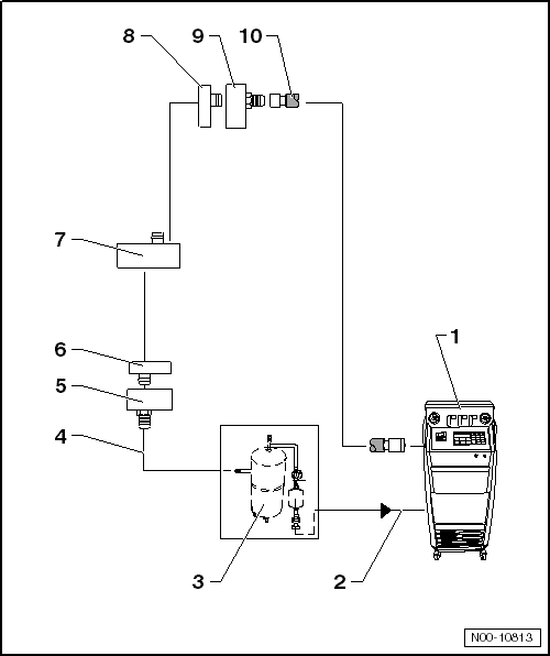
| 2 - |
A/C service station refrigerant hose |
| From the low pressure side of the service station (mostly blue) to
the output of the flushing device for refrigerant circuits. |
| 3 - |
Flushing equipment for refrigerant circuits |
| Different versions and different construction, for example
Refrigerant Circuit Flushing Device -VAS6336/1- or Air Conditioning
Flush Tool -VAS6337/1-. |
| With filter, viewing glass, security valve, heater, refrigerant
container, etc. (depending on version). |
| Depending on the construction of the A/C service station and of
refrigerant circuit flushing device, a check-valve may be installed at
output of refrigerant circuit flushing device (to guarantee correct
direction of refrigerant flow during flushing). |
| 4 - |
Charge hose for refrigerant circuit flushing device |
| From the high pressure side connection of the A/C compressor on the
refrigerant circuit (smaller diameter) to input of Refrigerant Circuit
Flushing Device -VAS6336/1- or Air Conditioning Flush Tool -VAS6337/1A-. |
| 5 - |
Adapter to connection for high pressure side on refrigerant circuit |
| The Refrigerant Circuits Adapter Set 1 - Adapter 3 -VAS6338/3- from
the Refrigerant Circuits Adapter Set 1 -VAS6338/1- |
Note
| If the Refrigerant Circuits Adapter Set - Adapter 40 -VAS6338/40- is
available, the filler hose can be directly attached to the A/C
compressor.
|
| 6 - |
High pressure side refrigerant line from A/C compressor |
Note
| Is not used if the Refrigerant Circuits Adapter Set - Adapter 40
-VAS6338/40- is available. |
| – |
Remove the centering pin from the refrigerant line so that the
Refrigerant Circuits Adapter Set 1 - Adapter 3 -VAS6338/3- fits. |
| 7 - |
Electrically-driven A/C compressor |
| The A/C compressor is flushed in the flow direction (from the low
pressure side input to the high pressure side output) |
| So that as much refrigerant oil as possible is flushed out of the
A/C compressor, the A/C compressor must be positioned so that the high
pressure side output is as low as possible. |
| 8 - |
Low pressure side refrigerant line to A/C compressor |
Note
| Is not used if the Refrigerant Circuits Adapter Set - Adapter 41
-VAS6338/41- is available. |
| – |
Remove the centering pin from the refrigerant line so that the
Refrigerant Circuits Adapter Set 1 - Adapter 6 -VAS6338/6- fits. |
| 9 - |
Adapter for connecting low pressure side to refrigerant circuit |
| The Refrigerant Circuits Adapter Set 1 - Adapter 6 -VAS6338/6- from
the Refrigerant Circuits Adapter Set 1 -VAS6338/1- |
Note
| If the Refrigerant Circuits Adapter Set - Adapter 41 -VAS6338/41- is
available, the filler hose can be directly attached to the A/C
compressor.
|
| 10 - |
A/C service station refrigerant hose |
| From the A/C service station high pressure side (mostly colored red)
to the connection on the low pressure line, or directly on the A/C
compressor with the Refrigerant Circuits Adapter Set - Adapter 41
-VAS6338/41-. |
Note
The arrows in the following illustrations show the direction
of refrigerant flow while flushing. During flushing, refrigerant
flows in the o ...
The following table lists the different adapters necessary
to connect the service station to the refrigerant circuit, to
flush and to bypass the removed receiver/drye ...
Other materials:
Cleaning and caring for natural leather covers
First read and observe the introductory information
and safety warningsPlease contact a Volkswagen dealership or other qualified
workshop if you have any questions on cleaning and caring for the leather equipment
in your vehicle.
Care and use
Natural leather is sensitive as it does not have ...
Critical Point
Vehicle air conditioning systems make use of the
vaporization and condensation process. In this case, one works
with a substance which boils easily, designated as refrigerant.
The refrigerant employed is tetrafluoroethane R134a, which
bo ...
Exterior mirrors
Fig. 80 In the front doors: setting knob
for the mechanical exterior mirrors
Fig. 81 In the driver door: rotary knob
for the electric exterior mirrors
First read and observe the introductory information
and safety warnings
The exterior mirrors are adjusted by moving the setting knob or th ...
© 2016-2026 Copyright www.vwpolo.net

 Flushing Circuit Block Diagrams
 Adapter for Assembling Flushing Circuit