Volkswagen Polo Owners Manual: Changing bulbs in the front bumper
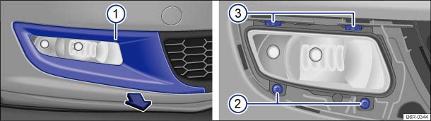
Fig. 182 In the front bumper, right-hand side: removing the cover and headlight
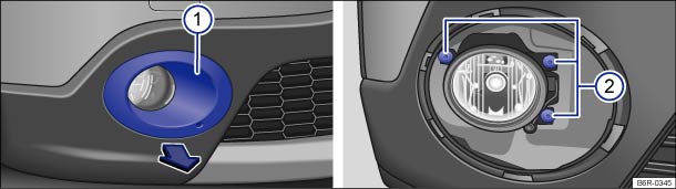
Fig. 183 In the front bumper, right-hand side: removing the cover and headlight
 First read and observe the introductory
information and safety warnings
First read and observe the introductory
information and safety warnings
| The actions should only be carried out in the specified order: | ||
|---|---|---|
| 1. | Follow the instructions on the checklist . | |
| 2. | Remove screwdriver with Torx bit and wire hook from the vehicle toolkit in the luggage compartment . | |
| 3. | Fit the wire hook in the cover recess ① and pull forward with cover in direction of arrow and remove. | |
| 4. | Remove the securing screws ② with the screwdriver. | |
| 5. | Release the guide catches ③ by pressing lightly on the retaining lugs. | |
| 6. | Pull the headlight out to the front slightly. | |
| 7. | Disconnect the electrical connector on the rear of the headlight by pressing the connector towards the headlight housing and simultaneously pressing the lug on the connector to disengage. Then remove the connector from the headlight. | |
| 8. | Turn the respective bulb holder anticlockwise as far as it will go and pull it out to the rear along with the bulb. | |
| 9. | Replace the defective bulb with a new bulb of the same type. | |
| 10. | Insert the bulb holder into the headlight and turn it clockwise as far as it will go. Make sure the bulb holder is fitted securely. | |
| 11. | Insert the connector into the appropriate bulb holder. The electrical connector must click into place . | |
| 12. | Insert the headlight. First fit it in position and then push it into the upper guides ③ until it engages. Note the position of the recesses in the bumper. | Insert the headlight. Note the position of the recesses in the bumper. |
| 13. | Push the headlight to the rear and tighten the securing screws ② with the screwdriver. | |
| 14. | Position the cover ① on the bumper and push in . Then check that it sits correctly. | |

 NOTICE
- Please ensure that the electrical connection on the headlight housing is positioned properly in order to prevent damage to the electrical system caused by water entering the system.
- When removing and refitting the headlight, make sure that the vehicle's paintwork is not damaged.

The illustrations show the right-hand headlight. The left-hand headlight is a mirror image of the one shown.
 Changing bulbs in the front headlights (Xenon)
Fig. 181 Rear view of right-hand
Xenon headlight: ① cornering light and ② turn signal
First read and observe the introductory
information and safety warnings
The headlight needs to be remov ...
 Changing the bulbs in the tail light cluster
Fig. 184 On the side of the
luggage compartment: removing the tail light cluster
Fig. 185 Tail light cluster:
removing the bulb holder
First read and observe the introductory
information and ...
Other materials:
A/C Pressure Switch -F129
Note
For switching pressures, removing and installing switches
and switch arrangement and version, see vehicle-specific
refrigerant circuit.
Refer to
→ Rep. Gr.87.
...
Diesel particulate filter
First read and observe the introductory information
and safety warningsThe diesel particulate filter filters out soot particles
in the exhaust gas. The soot particles gather in the filter and are burnt under
high temperatures periodically (regeneration). Heat produced can
warm the engine.
...
Decorative Trims, Replacing, Bonded Decorative Trims
Special tools and workshop equipment
required
Cartridge Gun -VAG1628-
Trim Removal Wedge -3409-
Wiring Harness Repair Set - Hot Air Blower -VAS1978/14A-
Materials ...
