Volkswagen Polo Service & Repair Manual: Tire Pressure Monitoring Sensor without Metal Valve, Removing and
Installing, Service Version
| Special tools and workshop equipment
required |
| – |
Remove the tire from the disc wheel. Refer to
→ Chapter „Tires, Mounting“. |
|
|
|
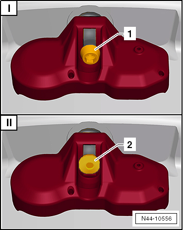
| See Which Version is Installed Before Starting Any Work. |
| The tire pressure monitoring sensor is attached to the valve
with an inner TORX screw -1- on the
Service version. |
| If the service version is installed, the following repair
procedure must be used. Refer to
→ Anchor. |
| II - Vehicles Before Customer Delivery |
| The tire pressure monitoring sensor is attached to the valve
with a square screw with a flat head -2-
on vehicles before customer delivery. |
| If the production version is installed, the following repair
procedure must be used. Refer to
→ Anchor. |
| – |
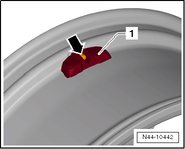
Remove the screw
-arrow- from the tire pressure
monitoring sensor -1-. |
|
|
|
| – |
Counterhold metal valve using retainer (for example 2 mm
spiral bore) while doing so. |
 Caution
| Clean the valve opening before installing the Tire
Pressure Monitoring Sensor. |
|
|
|
|
| – |
Press the tire pressure monitoring sensor
-1- onto the disc wheel (rim) and
tighten -arrow-. |
| – |
Counterhold metal valve using retainer (for example 2 mm
spiral bore) while doing so. |
 Note Note
| Visually check the valve after installing it and make sure
it is tight. The tire pressure monitoring sensor
-1- must not have any play when it
is installed and it must touch the supports in the rim bed. |
| Do not tighten the valve again to the tightening
specification after it has been installed. |
| Tightening Specifications |
| Refer to
→ Chapter „Overview - Tire Pressure Monitoring Sensor without
Valve“ |
|
|
|
Removing
–
Remove the union nut -1-.
–
Remove Tire Pressure Moni ...
Special tools and workshop equipment
required
Torque Wrench -VAG1410-
Perform the Following:
Remo ...
Other materials:
Fold Corrosion Servicing Notes
Corrosion on the Fold Edges, for Instance on the Hood, Door
or also the Rear Lid
–
Remove the corroded areas with
→ Chapter „Pneumatic Brush Grinder Set -VAS6446-“ or
→ Chapter „Brush Grinder Set ...
Structuring Component
Definition:
Structuring Component, Fine -ALN 775 108-
Edition 04/2013
Product Description
The Structuring Component, Fine -ALN 775 108- is a component
for the two-part HS top ...
Acoustic and optical ParkPilot signals at the rear of the vehicle
Fig. 121 ParkPilot screen display (colour)
Fig. 122 ParkPilot screen display (monochrome)
First read and observe the introductory information
and safety warnings
Key for displays
and
Meaning
Ⓐ
Scanned area ...
© 2016-2026 Copyright www.vwpolo.net

 Tire Pressure Monitoring Sensor with Valve, Removing and Installing
 Tire Pressure Monitoring Sensor without Valve, Removing and Installing,
Vehicle Before Customer Delivery
Tire Pressure Monitoring Sensor without Valve, Removing and Installing,
Vehicle Before Customer Delivery