Volkswagen Polo Service & Repair Manual: Vehicle Electrical System, General Repair Information
 Caution
| Follow the procedure in the repair manual when
disconnecting and connecting the battery. |
|
 WARNING
| Some tools are supplied with a tool safety clip,
which is slid over the tool points after using the tool,
in order to protect other workers from injuries and tool
points from damage. |
|
| Observe the current notes in the corresponding repair manual
for all repairs. |
| Observe country-specific regulations. |
| Before working on the electrical system, the battery ground
cable must be disconnected. By disconnecting the battery ground
cable (current disruption), the electrical system is guaranteed
to be safe to work on. Disconnecting the positive battery cable
is only required when removing the battery. |
| Before commencing repair work, always eliminate cause of
damage, for example, sharp body edges, faulty components,
corrosion etc. |
| Further information, for example, installing and removing
the individual components, can be found in the appropriate
Repair Manual. |
|
|
|
| Soldering is not permissible for repairs to the vehicle
electrical system. |
|
|
|
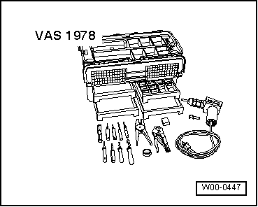
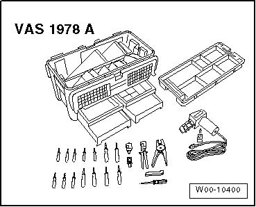
| Repair to the wiring harnesses and connectors on the vehicle
electrical system may only be performed using the Wiring Harness
Repair Set -VAS1978B- and with previous versions. Only use the
yellow wires from the Wiring Harness Repair Set -VAS1978B-. |
| Wiring harness repairs may not be performed again in the
wrapping of the vehicle-specific wiring harness and are to be
marked with yellow adhesive tape. This indicated a previous
repair. |
|
|
|
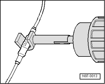
| Crimp connections must never be repaired. If necessary, lay
a wire parallel to the faulty wire. After crimping, crimp
connections must be heat-shrunk using hot air gun to prevent
moisture penetration. |
| Always observe also the supplementary notes for repairing
wiring harnesses on airbag- and seat belt tensioner systems,
fiber optic cables, CAN-Bus wires, antenna wires and wire
cross-sections up to 0.35 mm2. Refer
to
→ Chapter „Wires with Cross Section up to 0.35 mm
2, Repairing“. |
| A function test must be performed after every repair. If
necessary, check DTC memory, erase and/or bring systems into
basic setting. |
|
|
|
| If possible, do not loosen grounding straps from the body
(danger of corrosion). |
|
|
|
| Not all wire cross-sections in the vehicle are contained in
the Wiring Harness Repair Set -VAS1978B- and its previous
versions. If the required wire cross-section is not present, the
next greater cross-section must be used. |
| Shielded harnesses may be repaired. Camera system wires are
the exception. If faulty, the entire harness must be replaced. |
| Heat-resistant wires have been installed in the vehicle at
various locations, mainly in the engine compartment.
Heat-resistant wires can be recognized by their somewhat duller
and softer insulation. Only heat-resistant wires may be used to
repair these wires. |
|
|
|
© 2016-2026 Copyright www.vwpolo.net


