Volkswagen Polo Service & Repair Manual: Fiber-Optic Cable, Assembling
| Special tools and workshop equipment
required |
| Fiber-Optic Conductor Repair Set -VAS6223A- |
| Hose Cutting Pliers -VAS6228- |
| Vehicle Diagnostic Tester |
| It is very difficult to find the exact location of the
problem. Replace the damaged fiber-optic cable and lay a new
wire parallel to the defective fiber-optic cable. |
 Note Note
| Select the damaged fiber-optic cable components with the
“Guided Fault Finding” or “Guided Functions” from the Vehicle
Diagnostic Tester menu options. |
| A fiber-optic cable that needs repair is represented by a
“yellow” color. |
| – |
Choose “Guided Fault Finding” or “Guided Functions” in the
Vehicle Diagnostic Tester. Refer to Vehicle Diagnostic Tester. |
| – |
Assemble the fiber-optic cable. Refer to
→ Chapter „Fiber-Optic Cable, Assembling“. |
 Caution
| Do not bend the fiber-optic cable too much. The
bending radius must be no less than 25 mm. |
| Fiber optic cables must not be routed over sharp
edges. |
| The fiber-optic cable must not be dirty or touched
with bare fingers. |
| Fiber optic cables may not be heated. |
| It is not permitted to twist together 2 fiber optic
cables or one fiber optic cable with a copper wire. |
| Protect the connector and the connection box from
dust. Place the cap on the trunk. |
|
Caution
| Do not bend the fiber-optic cable too much. The
bending radius must be no less than 25 mm. |
| Fiber optic cables must not be routed over sharp
edges. |
| The fiber-optic cable must not be dirty or touched
with bare fingers. |
| Fiber optic cables may not be heated. |
| It is not permitted to twist together 2 fiber optic
cables or one fiber optic cable with a copper wire. |
| Protect the connector and the connection box from
dust. Place the cap on the trunk. |
|
|
|
|
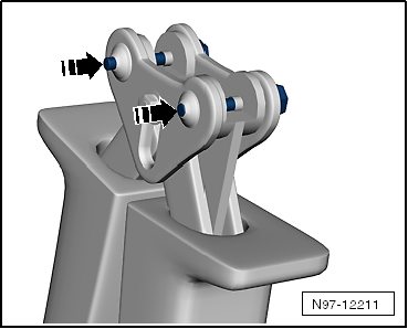
| Mount the Tool Head for the Fiber-Optic Repair Set - Pliers
-VAS6223/1-. |
|
|
|
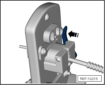
| – |
Remove the locking pin -arrows-. |
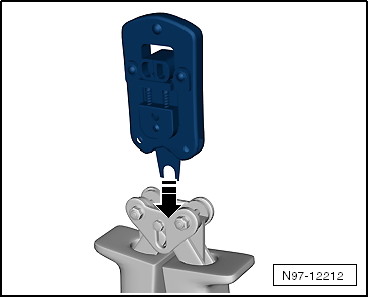
| – |
Remove the tool set -arrow- and
pull the locking pin back. |
|
|
|
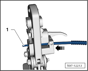
| Fiber Optic Cable, Cutting to Length |
| – |
Establish length of fiber optic cable required. |
| – |
Open the Fiber-Optic Repair Set - Pliers -VAS6223/1- and lay
the fiber-optic cable -1- in the
mount. |
| – |
Close the Fiber-Optic Repair Set - Pliers -VAS6223/1- to cut
the fiber-optic cable lengths. |
|
|
|
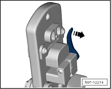
| – |
Open the Fiber-Optic Repair Set - Pliers -VAS6223/1-. |
| – |
Position the wire stripper in the lower position
-arrow-. |
| – |
Insert fiber-optic cable into the stripping station. |
| The end of the fiber-optic cable must be flush with the rear
side of the cutting pliers. |
|
|
|
| – |
Close the Fiber-Optic Repair Set - Pliers -VAS6223/1- until
the stop and keep closed. |
| – |
Bend the wire stripper upward -arrow-
and remove the fiber-optic cable. |
|
|
|
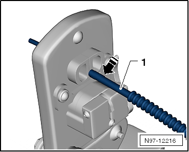
| Precision Cutting (Production of Optical End Face) |
| – |
Push the fiber-optic cable -1-
into the cutting station. |
| Insulation must make contact with cutting point stop. |
|
|
|
| – |
Close the Fiber-Optic Repair Set - Pliers -VAS6223/1- and
remove the wire. |
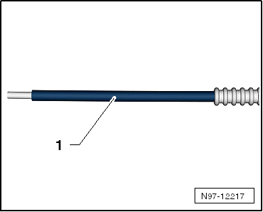
| – |
Visually inspect the wire -1-
to make sure that it was cut correctly and that there are no
burrs on the front surface. |
Note
| Fiber-optic cable is only to be placed on an absolutely
clean surface or held in hand. |
| Use the cap if there is a risk of the fiber-optic cable
surface becoming dirty. |
|
|
|
| Attaching Brass Pin Contact to Fiber-Optic Cable |
|
|
|
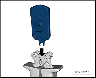
| – |
Change tool head -arrow-. |
| – |
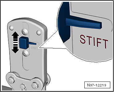
Slide the safeguard on the Fiber-Optic Repair Set - Pliers
-VAS6223/1- in direction of -arrow-
so that the word “Stift” (pin) is legible. |
|
|
|
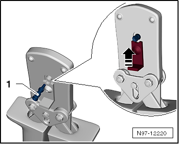
| – |
Insert a brass pin contact -1-
in the mount. |
| – |
Close the securing lever on the Fiber-Optic Repair Set -
Pliers -VAS6223/1- in direction of -arrow-. |
|
|
|
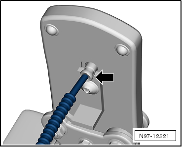
| – |
Insert the fiber-optic cable into the brass pin contact
-arrow- all the way up to the
threaded stop and then close the Fiber-Optic Repair Set - Pliers
-VAS6223/1-. |
| – |
Open the fiber-optic cable pliers and remove the fiber-optic
cable along with the brass contact pin. |
Caution
| Do not excessively bend or kink the fiber-optic
cables (minimum bending radius 25 mm). |
|
|
|
|
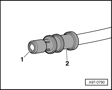
| – |
Make sure the brass pin contact -2-
is secured properly on the fiber-optic cable
-1-. |
| 4 crimped points must be visible on the brass connecting
pin. |
| The brass pin contact must not be able to be removed by hand
from fiber-optic cable. |
| The front surface of the fiber-optic cable is 0.01 to 0.1 mm
behind the brass pin contact (visual check). |
Note
| Connector couplings are available for connecting the
fiber-optic cables. Refer to Parts Catalog. |
| To install the new fiber optic cable in wiring harness
connector. Refer to
→ Chapter „Fiber-Optic Cable, Disconnecting from Wiring Harness
Connector“. |
|
|
|
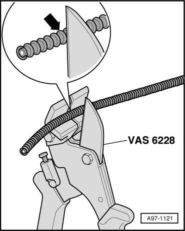
| Corrugated Tube, Install on Fiber Optic Cable |
| – |
Cut corrugated tube to appropriate length. |
| Use the Hose Cutting Pliers -VAS6228- or a sharp knife for
cutting. |
| The corrugated tube must not be cut through using a side
cutter under any circumstances |
| The corrugated tube must be cut on the wave peak
-arrow-, not in the wave trough. |
| The corrugated tube must audibly engage in the fiber-optic
cable housing when installing. |
|
|
|
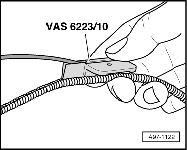
| – |
Guide the fiber-optic cable into the Fiber-Optic Repair Set
- Tube Tool -VAS6223/10- as shown. |
| – |
Position corrugated tube assembly pliers on slot on the
tube. |
| – |
Position crimping pliers for fiber-optic cable at slot of
corrugated tube. The fiber optic cable is then routed in the
corrugated tube. |
|
|
|
Removing
–
Unplug connector for fiber optic cable from appropriate
control unit.
–
Release the loc ...
Other materials:
Battery Safety Label
Battery Safety Label
1. -
When working in the area of batteries, fire, sparks, open
flame and smoking are prohibited. Avoid sparks when working with
cables and electrical devices, and from electrostatic discharge.
Avoid s ...
Cleaning and caring for natural leather covers
First read and observe the introductory information
and safety warningsPlease contact a Volkswagen dealership or other qualified
workshop if you have any questions on cleaning and caring for the leather equipment
in your vehicle.
Care and use
Natural leather is sensitive as it does not have ...
Windscreen wiper lever
Fig. 72 Operating the front windscreen
wiper
Fig. 73 Operating the rear window wiper
First read and observe the introductory information
and safety warnings
Move the windscreen wiper lever to the desired position
:
⓪
Switches ...
© 2016-2026 Copyright www.vwpolo.net


 Fiber-Optic Cable, Disconnecting from Wiring Harness Connector