Volkswagen Polo Service & Repair Manual: 4-Pin Heated Oxygen Sensor (HO2S), Removing and Installing
 Note Note
| Do not repair the heated oxygen sensor wires. Repairing may
result in malfunctions. |
| Use the faulty sensor as a guide for installing all of the
accompanying attachments, cable ties or marking bands. |
| If necessary, identify the heated oxygen sensor (HO2S) using
the protective tube. Refer to
→ Chapter „Oxygen Sensor Unit Protective Pipes“. |
| – |
Remove the faulty oxygen sensor. |
|
|
|
| – |
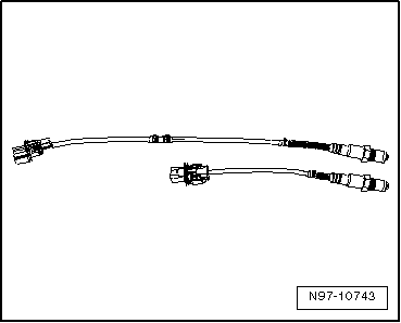
Lay both of the oxygen sensor next to each other so the
sensor housings are the same level. |
|
|
|
| – |
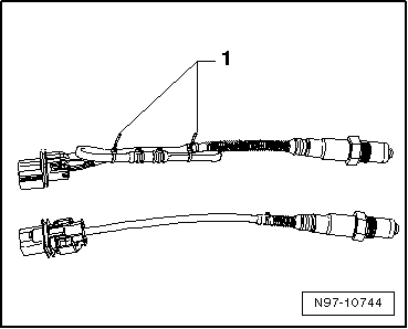
Tie the excess length of the sensor (approximately 50 to 250
mm) back so it is the same length as the faulty sensor and
secure it with cable ties -1-. |
| – |
Check if the oxygen sensor connector housing is compatible
with the vehicle electrical system side. |
| – |
If necessary, replace the vehicle electrical system
connector with the provided oxygen sensor connector housing.
Refer to
→ Chapter „Contact Housings and Connectors, Repairing“. |
Note
| Only replace the connector housing on older vehicles. The
connector housing is correct on new vehicles. |
| Check the pin assignment. The pins in the new connector
housing are color coded. |
| The packaging for the new heated oxygen sensor contains
additional information. |
| – |
Install the new oxygen sensor in the vehicle. |
|
|
 |
Note
Use the faulty sensor as a guide for installing all of the
accompanying attachments, cable ties or marking bands.
Do ...
Other materials:
Rims
First read and observe the introductory information
and safety warningsThe design of the wheel bolts is matched to the rims.
If different rims are fitted, the correct wheel bolts with the right length and
correctly shaped bolt heads must be used. This ensures that wheels are fitted securely
...
Interior monitoring system and anti-tow alarm
Fig. 26 Next to the driver seat: button
for switching off the interior monitoring system and anti-tow alarm
First read and observe the introductory information
and safety warnings
The interior monitoring system will trigger an alarm if movement is detected
inside the vehicle when the vehicl ...
Overview of the driver side
Fig. 5 Overview of the driver side
(left-hand drive vehicles)
Fig. 6 Overview of the driver side
(right-hand drive vehicles)
Key for and :
Vent
,
Lever for:
Main beam headlights
Headlight flasher
Turn signal
Parking lig ...
© 2016-2026 Copyright www.vwpolo.net



 6-Pin Universal Oxygen Sensor, Removing and Installing