Volkswagen Polo Service & Repair Manual: Vehicle Diagnostic Tester, Connecting
| Special tools and workshop equipment
required |
| Vehicle Diagnostic Tester |
| Vehicle Diagnosis System - Diagnostic Cable -VAS5051/6A- (5
m) |
| Vehicle Diagnosis System - Updated Cable - 3m -VAS5051/5A-
(3 m) |
 WARNING
| During road tests using a vehicle diagnostic and
information system, there is the hazard of extreme to
lethal injuries! |
| If vehicle diagnostic and information system is
deposited in the action area of an airbag during a road
test, here is the hazard of extreme to lethal injuries
in the event the airbag deploys! |
| During road tests, have a person sitting in the rear
seat to operate the vehicle diagnostic and information
system. |
|
 Note Note
| All of the procedures described such as adaptations and
coding can be performed with the Vehicle Diagnostic Tester. |
| All work instructions can be reached in the operating modes
“Guided Fault Finding” and “Guided Functions”. |
| – |
Connect the Vehicle Diagnostic Tester. Refer to
→ Chapter „Vehicle
Diagnostic Tester, Connecting“. |
Note
| Follow the current operating instructions for the Vehicle
Diagnostic Tester, which can be displayed by selecting the
“Administration” and “operator's handbook” buttons. |
Note
| For the diagnosis, only the diagnostic cables listed above
are to be used since only these are equipped with CAN wires and
permit a CAN diagnostic or CAN communication. |
| Connect the Vehicle Diagnostic Tester. |
| – |
Apply the parking brake. |
| – |
In vehicles with automatic transmission, move the selector
lever to the “P” or “N” position. |
| – |
In vehicles with manual transmissions, move the shift lever
to the neutral position. |
|
|
|
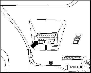
| – |
With the ignition switched off, connect the Vehicle
Diagnostic Tester with the Vehicle Diagnosis System - Diagnostic
Cable -VAS5051/6A- to the diagnostic connection
-arrow- in the vehicle.
|
| – |
Turn off all electrical consumers. |
Note
| The connection of all other and the following diagnostic
operation system or vehicle diagnosis and service system occurs
in the previously described sequence. |
|
|
|
Apply the parking brake.
–
In vehicles with automatic transmission, move the selector
lever to the “P” or “N” posi ...
Other materials:
Bonding Agent
Definition:
Bonding Agent -LLS MAX 015-, plastic
Edition 10/2012
Product Description
The Bonding Agent -LLS MAX 015- is a universal
single-component bonding agent for all sta ...
Tire Sidewall Swelling
A swelling in the flank of the tire indicates that the
substructure of the carcass has been damaged.
Typical causes for such damage include, for example, driving
over curbs at a sharp angle.
...
Electric panorama sliding/tilting glass roof – function
First read and observe the introductory information
and safety warnings
Convenience opening and closing
The electric panorama sliding/tilting glass roof can be opened and closed from
the outside with the vehicle key.
Press and hold the locking or unlocking button on the vehicle key. The e ...
© 2016-2026 Copyright www.vwpolo.net


 Vehicle Diagnostic Tester, Connecting, Golf MY 1998 through 2003