Volkswagen Polo Owners Manual: Tyre Pressure Loss Indicator
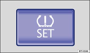
Fig. 124 In the stowage compartment on the front passenger side: button for the Tyre Pressure Loss Indicator
 First read and observe the introductory information
and safety warnings
First read and observe the introductory information
and safety warnings The Tyre Pressure Loss Indicator uses data from the ABS sensors and other functions to check the speed of rotation and the rolling circumference of the individual wheels. Any change in the rolling circumference of one or more wheels is shown by the Tyre Pressure Loss Indicator in the instrument cluster.
Changes in the rolling circumference
The rolling circumference of a tyre can change:
- If the tyre pressure has been changed manually.
- If the tyre pressure is too low.
- If the tyre has structural damage.
- If the vehicle is loaded more heavily on one side.
- If the wheels on one axle are loaded more heavily, e.g. high load level.
- If snow chains have been fitted.
- If a temporary spare wheel has been fitted.
- If one wheel per axle has been changed.
In certain circumstances, the Tyre Pressure Loss Indicator
 may become slow or may not display
anything, e.g. with a sporty driving style, in winter driving conditions, on unpaved
roads, or when driving with snow chains.
may become slow or may not display
anything, e.g. with a sporty driving style, in winter driving conditions, on unpaved
roads, or when driving with snow chains.
Calibrating the Tyre Pressure Loss Indicator
The Tyre Pressure Loss Indicator will have to be re-synchronised after changing the tyre pressure, or after changing one or more wheels. This also applies when wheels are swapped, e.g. from the front to the rear.
- Switch on the ignition.
- Press and hold the button until an acoustic confirmation signal is emitted.
During normal vehicle operation, the system calibrates itself independently to the fitted tyres and the tyre pressures filled by the driver. The calibrated values are stored and monitored after a long journey at various speeds.
If the wheels are loaded more heavily than normal, e.g. if the vehicle is carrying heavy payload, the tyre pressure must be raised to the recommended full-load tyre pressure before synchronisation .

 WARNING

 Indicator lamp for the tyre monitoring system
First read and observe the introductory information
and safety warnings
Lit up
Possible cause
Solution
The
tyre pressure o ...

Other materials:
Wiring Harness Repair Set - Wire Strippers -VAS1978/3
The Wiring Harness Repair Set - Wire Strippers -VAS1978/3-
is used for professional stripping and cutting of wires.
The Wiring Harness Repair Set - Wire Strippers -VAS1978/3-
is a component of the Wiring Harness Repair Set -VAS1978B- and
...
General Information
Battery Charger -VAS5906-
WARNING
Risk of injury. Follow all Warnings and Safety
Precautions. Refer to
→ Chapter „Warnings and Safety Precautions“.
...
Autogas
Fig. 133 In the upper section of the centre
console: switch for Autogas
First read and observe the introductory information
and safety warnings When the vehicle is restarted, the last
manually selected operating mode will be adopted automatically. If, for example,
autogas mode was activa ...
