Volkswagen Polo Service & Repair Manual: Tire Pressure Monitoring Sensor with Valve, Removing and Installing
| – |
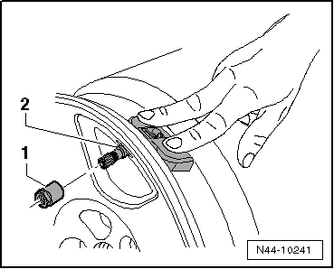
Remove the union nut -1-. |
| – |
Remove Tire Pressure Monitoring Sensor-2-
from rim well. |
 Caution
| Clean the valve opening before installing the Tire
Pressure Monitoring Sensor. |
|
|
|
|
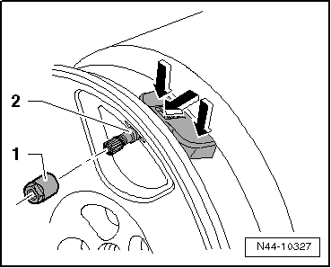
| – |
Insert the Tire Pressure Monitoring Sensor-2-
with new seal and sealing washer and press it on the spots
marked with the -arrows- into the
disc wheel (rim). |
| – |
Press the Tire Pressure Monitoring Sensor-2-
on the spots marked with the -arrows-
into the disc wheel (rim). |
| Screw on union nut -1- from
outside onto tire pressure sensor. |
|
|
|
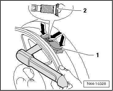
| – |
Press the Tire Pressure Monitoring Sensor-1-
on the spots marked with the -arrows-
into the rim and tighten the union nut to 8 Nm. |
Caution
| Only tighten the union nut to the tightening
specification. |
| Sealing washer -2-
becomes slightly deformed when doing this. |
| The sealing washer can be installed one time only.
At every installation, replace the sealing washer and
rubber seal. |
| Do not tighten the union nut again. This will damage
the seal and it will leak. |
|
| Tightening Specifications |
| Refer to
→ Chapter „Overview - Tire Pressure Monitoring Sensor with
Valve“ |
|
|
|
Special tools and workshop equipment
required
Torque Wrench -VAG1410-
Perform the Following:
Remo ...
Other materials:
“2 Color” Visual Indicator, Checking
WARNING
Risk of injury. Follow all Warnings and Safety
Precautions. Refer to
→ Chapter „Warnings and Safety Precautions“.
Visual Indicator General Informatio ...
Vehicle Registration Documents Since 01/10/2005
The implementation of EU guideline 1999/37/EG "Vehicle
registration documents" in national legislation and legal data
protection requirements have made the introduction of new, fraud
resistant registration documents necessary.
...
Flushing Not Necessary
Note
For vehicles with an electrically-driven A/C compressor,
de-energize the high voltage system before removing the A/C
compressor. Refer to
→ Electrical System Hybrid; Rep. Gr.93.
–
Dischar ...
© 2016-2026 Copyright www.vwpolo.net


 Tire Pressure Monitoring Sensor without Metal Valve, Removing and
Installing, Service Version
Tire Pressure Monitoring Sensor without Metal Valve, Removing and
Installing, Service Version