Volkswagen Polo Service & Repair Manual: Fiber-Optic Cable, Assembling
| Special tools and workshop equipment
required |
| Fiber-Optic Conductor Repair Set -VAS6223A- |
| Hose Cutting Pliers -VAS6228- |
| Vehicle Diagnostic Tester |
| It is very difficult to find the exact location of the
problem. Replace the damaged fiber-optic cable and lay a new
wire parallel to the defective fiber-optic cable. |
 Note Note
| Select the damaged fiber-optic cable components with the
“Guided Fault Finding” or “Guided Functions” from the Vehicle
Diagnostic Tester menu options. |
| A fiber-optic cable that needs repair is represented by a
“yellow” color. |
| – |
Choose “Guided Fault Finding” or “Guided Functions” in the
Vehicle Diagnostic Tester. Refer to Vehicle Diagnostic Tester. |
| – |
Assemble the fiber-optic cable. Refer to
→ Chapter „Fiber-Optic Cable, Assembling“. |
 Caution
| Do not bend the fiber-optic cable too much. The
bending radius must be no less than 25 mm. |
| Fiber optic cables must not be routed over sharp
edges. |
| The fiber-optic cable must not be dirty or touched
with bare fingers. |
| Fiber optic cables may not be heated. |
| It is not permitted to twist together 2 fiber optic
cables or one fiber optic cable with a copper wire. |
| Protect the connector and the connection box from
dust. Place the cap on the trunk. |
|
Caution
| Do not bend the fiber-optic cable too much. The
bending radius must be no less than 25 mm. |
| Fiber optic cables must not be routed over sharp
edges. |
| The fiber-optic cable must not be dirty or touched
with bare fingers. |
| Fiber optic cables may not be heated. |
| It is not permitted to twist together 2 fiber optic
cables or one fiber optic cable with a copper wire. |
| Protect the connector and the connection box from
dust. Place the cap on the trunk. |
|
|
|
|
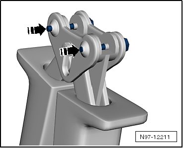
| Mount the Tool Head for the Fiber-Optic Repair Set - Pliers
-VAS6223/1-. |
|
|
|
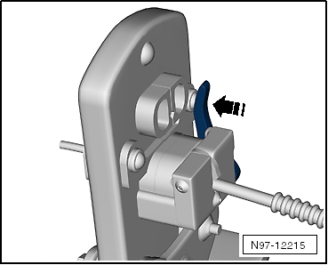
| – |
Remove the locking pin -arrows-. |
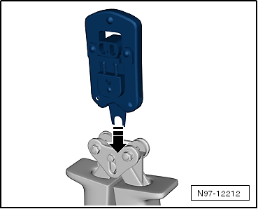
| – |
Remove the tool set -arrow- and
pull the locking pin back. |
|
|
|
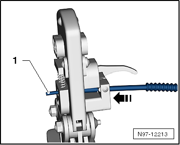
| Fiber Optic Cable, Cutting to Length |
| – |
Establish length of fiber optic cable required. |
| – |
Open the Fiber-Optic Repair Set - Pliers -VAS6223/1- and lay
the fiber-optic cable -1- in the
mount. |
| – |
Close the Fiber-Optic Repair Set - Pliers -VAS6223/1- to cut
the fiber-optic cable lengths. |
|
|
|
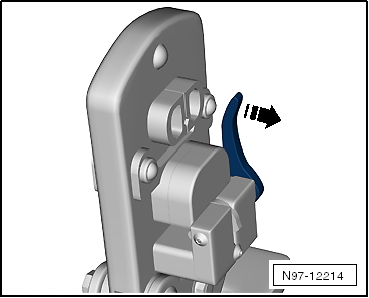
| – |
Open the Fiber-Optic Repair Set - Pliers -VAS6223/1-. |
| – |
Position the wire stripper in the lower position
-arrow-. |
| – |
Insert fiber-optic cable into the stripping station. |
| The end of the fiber-optic cable must be flush with the rear
side of the cutting pliers. |
|
|
|
| – |
Close the Fiber-Optic Repair Set - Pliers -VAS6223/1- until
the stop and keep closed. |
| – |
Bend the wire stripper upward -arrow-
and remove the fiber-optic cable. |
|
|
|
| Precision Cutting (Production of Optical End Face) |
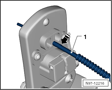
| – |
Push the fiber-optic cable -1-
into the cutting station. |
| Insulation must make contact with cutting point stop. |
|
|
|
| – |
Close the Fiber-Optic Repair Set - Pliers -VAS6223/1- and
remove the wire. |
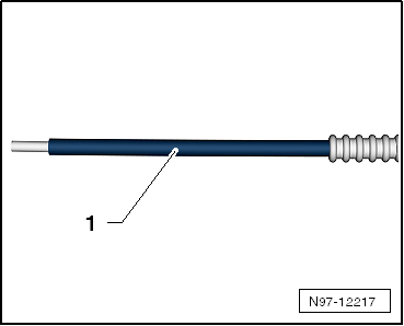
| – |
Visually inspect the wire -1-
to make sure that it was cut correctly and that there are no
burrs on the front surface. |
Note
| Fiber-optic cable is only to be placed on an absolutely
clean surface or held in hand. |
| Use the cap if there is a risk of the fiber-optic cable
surface becoming dirty. |
|
|
|
| Attaching Brass Pin Contact to Fiber-Optic Cable |
|
|
|
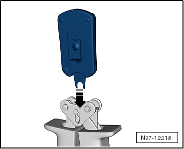
| – |
Change tool head -arrow-. |
| – |
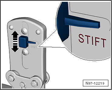
Slide the safeguard on the Fiber-Optic Repair Set - Pliers
-VAS6223/1- in direction of -arrow-
so that the word “Stift” (pin) is legible. |
|
|
|
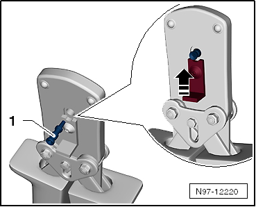
| – |
Insert a brass pin contact -1-
in the mount. |
| – |
Close the securing lever on the Fiber-Optic Repair Set -
Pliers -VAS6223/1- in direction of -arrow-. |
|
|
|
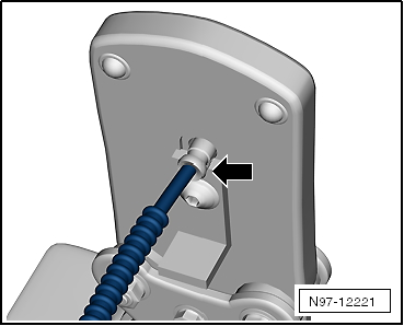
| – |
Insert the fiber-optic cable into the brass pin contact
-arrow- all the way up to the
threaded stop and then close the Fiber-Optic Repair Set - Pliers
-VAS6223/1-. |
| – |
Open the fiber-optic cable pliers and remove the fiber-optic
cable along with the brass contact pin. |
Caution
| Do not excessively bend or kink the fiber-optic
cables (minimum bending radius 25 mm). |
|
|
|
|
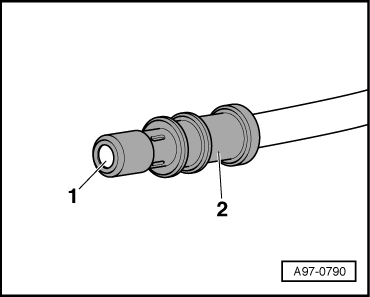
| – |
Make sure the brass pin contact -2-
is secured properly on the fiber-optic cable
-1-. |
| 4 crimped points must be visible on the brass connecting
pin. |
| The brass pin contact must not be able to be removed by hand
from fiber-optic cable. |
| The front surface of the fiber-optic cable is 0.01 to 0.1 mm
behind the brass pin contact (visual check). |
Note
| Connector couplings are available for connecting the
fiber-optic cables. Refer to Parts Catalog. |
| To install the new fiber optic cable in wiring harness
connector. Refer to
→ Chapter „Fiber-Optic Cable, Disconnecting from Wiring Harness
Connector“. |
|
|
|
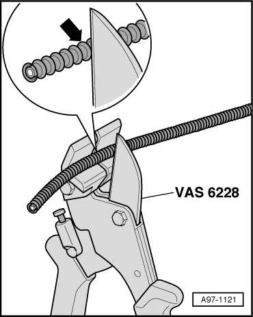
| Corrugated Tube, Install on Fiber Optic Cable |
| – |
Cut corrugated tube to appropriate length. |
| Use the Hose Cutting Pliers -VAS6228- or a sharp knife for
cutting. |
| The corrugated tube must not be cut through using a side
cutter under any circumstances |
| The corrugated tube must be cut on the wave peak
-arrow-, not in the wave trough. |
| The corrugated tube must audibly engage in the fiber-optic
cable housing when installing. |
|
|
|
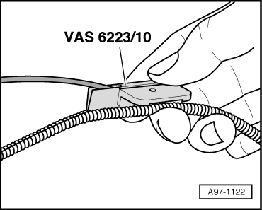
| – |
Guide the fiber-optic cable into the Fiber-Optic Repair Set
- Tube Tool -VAS6223/10- as shown. |
| – |
Position corrugated tube assembly pliers on slot on the
tube. |
| – |
Position crimping pliers for fiber-optic cable at slot of
corrugated tube. The fiber optic cable is then routed in the
corrugated tube. |
|
|
|
Removing
–
Unplug connector for fiber optic cable from appropriate
control unit.
–
Release the loc ...
Other materials:
Current Draw Test
WARNING
Batteries that have a light yellow visual indicator
do not have to be tested or charged. Jump starting must
not be used!
There is a risk of explosion during testing,
...
Silicone Remover -LLS MAX 007
Definition:
Silicone Remover -LLS MAX 007-
Edition 10/2008
Product Description
The Silicone Remover -LLS MAX 007- is a water-based,
reduced-solvent cleaning agent that is ric ...
Battery, Testing using Midtronics Battery Tester -MCR340VKT
Requirements
WARNING
Read and follow the Safety Precautions when working
with batteries. Refer to
→ Chapter „Warnings and Safety Precautions“.
...
© 2016-2026 Copyright www.vwpolo.net


 Fiber-Optic Cable, Disconnecting from Wiring Harness Connector