Volkswagen Polo Service & Repair Manual: Antenna Wires, Repairing
Aerial Cable Repair Set -VAS6720
| Special tools and workshop equipment
required |
| Repair Set, Aerial Cable -VAS6720- |
| Checking the Antenna Wire. Refer to |
| Replacing the Tool Head. Refer to |
| Cutting the Antenna Wire. Refer to |
| Removing the Insulation from the Shield. Refer to |
| Removing the Outer Jacket of Insulation. Refer to |
| Removing the Inner Insulation. Refer to |
| Crimping the Inner Conductor. Refer to |
| Crimping the Outer Conductor. Refer to |
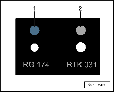
| The Repair Set, Aerial Cable -VAS6720- makes it possible to
perform a quality repair on antenna wires RG 174 (blue) and RTK
031 (black). The set contains the insulation removal tools and
the crimping tools for both antenna wires. Moreover, all the
individual parts needed are in the kit. Only the zero-coded
coupler (green) is needed. All other connection wires for the
different Infotainment systems can be found in the Parts Catalog
in table 035-XX. These adapter antenna wires must always be
ordered separately depending on the vehicle type. All part
numbers needed for reordering can be found in this table. The
each compartment in the kit has a part number. The repair kit is
based on the Wiring Harness Repair Set VAS1978B. |
 Note Note
| Additional information: Repair Set, Aerial Cable -VAS6720-
Operating Instructions. |
| Checking the Antenna Wire: |
|
|
|
| Before starting the repair, determine which antenna wire
using the gauge. |
| -2- System RTK 031 = gray |
| The adjusters on the heads of the tools are color coded on
both systems. |
| – |
Select the appropriate tool head based on the antenna wire
test. Refer to
→ Anchor. |
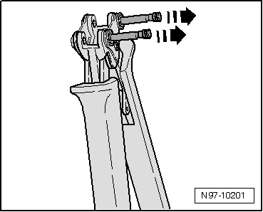
| – |
Open the handle on the pliers all the way. |
|
|
|
| – |
Release and remove both locking pins in direction of
-arrows- from the handle. |
|
|
|
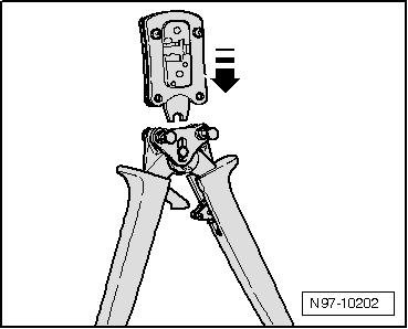
| – |
Attach the necessary tool head to the handle from the top in
direction of -arrow-. |
|
|
|
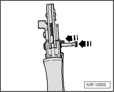
| – |
Insert the pins in direction of
-arrows- into the handle in order to lock the tool head
into place. |
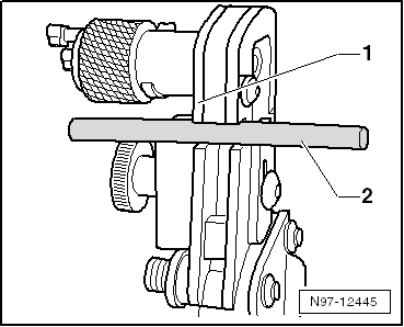
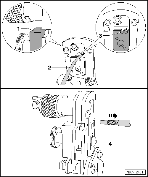
| Cutting the Antenna Wire: |
|
|
|
| – |
Slide the antenna wire -2- into
the cutting device -1-. |
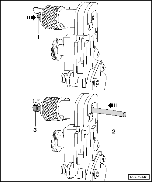
| – |
Close the tool then open it again. |
| – |
Pull the antenna wire out of the cutting device. |
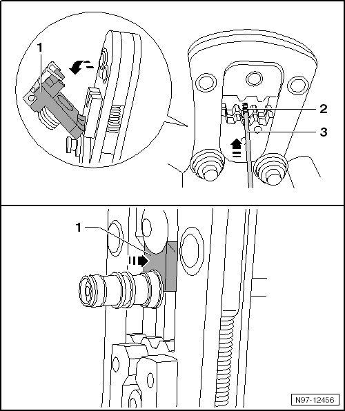
| Removing the Insulation from the
Shield: |
|
|
|
| – |
Push the locking pin -1- all the way
into the rotating cutting piece. |
| – |
Push the antenna wire -2- all the way
into the rotating cutting piece. The locking pin
-3- can not be seen completely. |
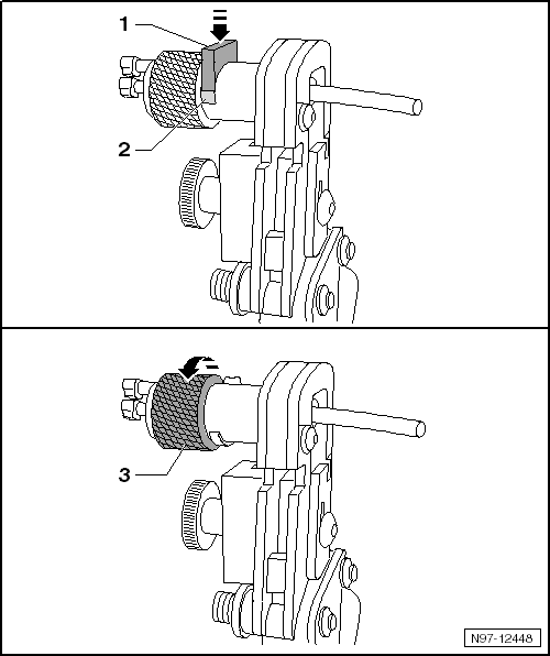
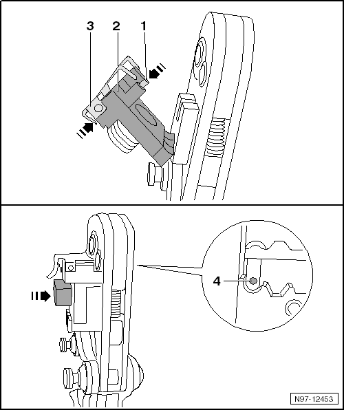
| – |
Push the blade holder -1- against the
axle of the rotating cutting segment until it locks into place. The gap
-2- under the blade holder is completely
closed. |
| – |
Hold the antenna wire so that it cannot turn. |
| – |
Turn the rotating cutting segment -3- 2
times in direction of -arrow- until it
starts to turn easily. |
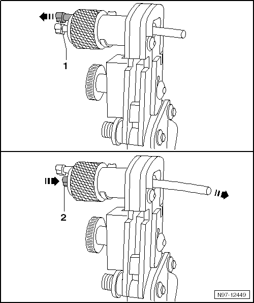
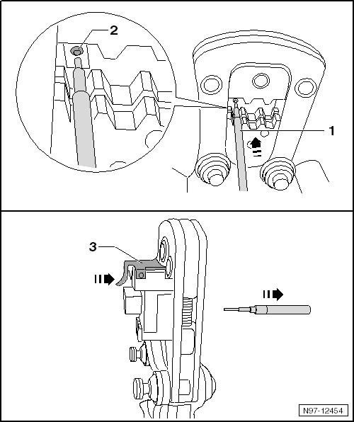
| – |
Pull the release pin -1-. The blade
holder unlocks and separates from the antenna wire. |
| – |
Push the locking pin -2- all the way
into the rotating cutting piece. The antenna wire is pushed out of the
rotating cutting segment. |
| – |
Remove insulation from the antenna wire. |
| – |
Remove any insulation remaining on the rotating cutting segment. |
| Removing the Outer Jacket of
Insulation: |
|
|
|
| – |
Slide the antenna wire -2- in the mount
-3- into the tool head until it stops
-1-. |
| – |
Close the tool then open it again. |
| – |
Remove the antenna wire -4-. |
| Removing the Inner Insulation: |
|
|
|
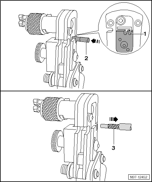
| – |
Push the antenna wire -2- in the mount
-1- all the way into the tool head. |
| – |
Close the tool then open it again. |
| – |
Remove the antenna wire -3-. |
| Crimping the Inner Conductor: |
|
|
|
| – |
Select the appropriate tool head based on the antenna wire test.
Refer to
→ Anchor. |
| – |
Unfold the positioner -2-. |
| – |
Open the positioning plate -3-. The
positioning plate swivels upward. |
| – |
Push the inner contact -1- all the way
into the positioner and loosen the positioning plate. The inner contact
is attached. |
| – |
Fold the positioner back in. The inner contact
-4- is positioned inside the tool head. |
| – |
Slide the antenna wire -1- into the
inner contact -2- in the tool head. Hold
the positioner tight while doing this. |
| – |
Lock the tool until it opens by itself. |
| – |
Open the positioning plate -3- and pull
out the antenna wire. |
| Crimping the Outer Conductor: |
|
|
|
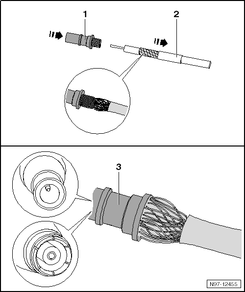
| – |
Slide the sleeve -2- and outer contact
-1- over the inner conductor. The knurled
contact piece must be pushed under the shield -3-,
but over the aluminum foil. |
| – |
Slide the outer contact -4- all the way
on. Make the bushing/pin fit correctly when doing this. |
| – |
Push the sleeve -3- up to the outer
contact. |
| – |
Open the tool and fold out the positioner -1-. |
| – |
Position the outer contact -2- in the
tool head on the contact edge -4-. |
| – |
Close the tool then open it again. |
| – |
Pull out the antenna wire. |
Removing
–
Unplug connector for fiber optic cable from appropriate
control unit.
–
Release the loc ...
Other materials:
Two-Part Fine Filling Paste
Definition:
Two-Part Fine Filling Paste -LSP 784 002 A2-
Edition 06/2011
Product Description
The two-part fine filling paste is a very fine thixotropic
polyester filling past ...
Two-Part HS Performance Clear Coat
Definition:
Two-Part HS Performance Clear Coat -LZK 769 K06 A5-
Edition 08/2012
Product Description
The two-part HS performance clear coat is a high-gloss, VOC
compliant high ...
A/C Service Station, Connecting for Measuring and Testing
Caution
If it is suspected that chemicals were added to the
refrigerant circuit to seal leaks, do not connect the
A/C service station and do not extract the refrigerant.
...
© 2016-2026 Copyright www.vwpolo.net

 Fiber-Optic Cable, Disconnecting from Wiring Harness Connector