Volkswagen Polo Owners Manual: Using the cruise control system
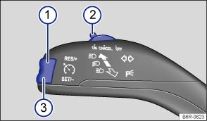
Fig. 123 On the left of the steering column: button and switch for the CCS
 First read and observe the introductory information
and safety warnings
First read and observe the introductory information
and safety warnings | Function | Switch position, switch control | Action |
|---|---|---|
| Switching on the CCS. | Switch ② in position

 . . |
The system is switched on. No speed has yet been stored and the speed is not yet being controlled. |
| Activating the CCS. | Press button ③


 . . |
The current speed is stored and controlled. |
| Switching off the CCS control temporarily. | Switch ② in position


 OR: depress the brake or clutch pedal. |
Control is switched off temporarily. The speed is stored in the memory. |
| Resuming CCS control. | Press button ①

 . . |
The stored speed is reactivated and controlled. |
| Increasing the set speed (during CCS control). | Press button ①
briefly to increase
the speed in small steps of 1 km/h (1 mph) and to save. |
The vehicle accelerates actively until it reaches the new set speed. |
| Press and hold down button ①
continuously to continuously
increase the speed; the increased speed setting will be saved when you release
the button. |
||
| Decreasing the set speed (during CCS control). | Press button ③
briefly to reduce
the stored speed in small steps of 1 km/h (1 mph) and to save. |
By easing off the accelerator and without actively braking, the system will decrease the speed until the new set speed is reached. |
| Press and hold button ③
to decrease the speed continuously.
The new speed setting will be saved when you release the button. |
||
| Switching off the CCS. | Switch ② in position
 .
. |
The system is switched off. The stored speed will be deleted. |
The mph figures given in brackets in the table relate exclusively to instrument clusters with mile readings.
Driving downhill with CCS
If the CCS cannot maintain the vehicle speed when driving downhill, brake the vehicle with the foot brake and shift down gear if necessary.
Automatic switch-off
The control will be switched off automatically or switched off temporarily:
- If the system detects a fault that could impair the function of the CCS.
- If the vehicle speed is higher than the stored speed for an extended period with the accelerator pedal depressed.
- If the brake pedal or clutch pedal is depressed.
- If you change gear on a manual gearbox.
- If the airbag is triggered.
 Indicator lamp
First read and observe the introductory information
and safety warnings
Lit up
Possible cause
Cruise control system (CCS) is controlling th ...

Other materials:
Aqua Premium System (Rim Paintwork)
Definition:
Water-Based Metallic Base Paint -LWG 056 1H7 A1-
Edition 04/2013
Product Description
Description of rim paintwork using Water-Based Metallic Base
Paint -LWG 056 1 ...
Changing bulbs in the front headlights (halogen H4)
Fig. 178 Rear view of the
right-hand H4 headlight with plastic covers: ① dipped beam and main beam, ② turn
signal and ③ side light
Fig. 179 Rear view of the
right-hand H4 headlight with rubber cover: ① dipped beam and main beam, ② turn
signal and ③ side light
First read and o ...
Warning and indicator lamps
The warning and indicator lamps indicate various warnings , faults or certain
functions. Some warning and indicator lamps light up when the ignition is
switched on and should go out once the engine is running or the vehicle is in
motion.
Depending on the vehicle's equipment level, additional ...
