Volkswagen Polo Owners Manual: Using the cruise control system
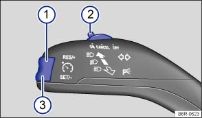
Fig. 123 On the left of the steering column: button and switch for the CCS
 First read and observe the introductory information
and safety warnings
First read and observe the introductory information
and safety warnings | Function | Switch position, switch control | Action |
|---|---|---|
| Switching on the CCS. | Switch ② in position

 . . |
The system is switched on. No speed has yet been stored and the speed is not yet being controlled. |
| Activating the CCS. | Press button ③


 . . |
The current speed is stored and controlled. |
| Switching off the CCS control temporarily. | Switch ② in position


 OR: depress the brake or clutch pedal. |
Control is switched off temporarily. The speed is stored in the memory. |
| Resuming CCS control. | Press button ①

 . . |
The stored speed is reactivated and controlled. |
| Increasing the set speed (during CCS control). | Press button ①
briefly to increase
the speed in small steps of 1 km/h (1 mph) and to save. |
The vehicle accelerates actively until it reaches the new set speed. |
| Press and hold down button ①
continuously to continuously
increase the speed; the increased speed setting will be saved when you release
the button. |
||
| Decreasing the set speed (during CCS control). | Press button ③
briefly to reduce
the stored speed in small steps of 1 km/h (1 mph) and to save. |
By easing off the accelerator and without actively braking, the system will decrease the speed until the new set speed is reached. |
| Press and hold button ③
to decrease the speed continuously.
The new speed setting will be saved when you release the button. |
||
| Switching off the CCS. | Switch ② in position
 .
. |
The system is switched off. The stored speed will be deleted. |
The mph figures given in brackets in the table relate exclusively to instrument clusters with mile readings.
Driving downhill with CCS
If the CCS cannot maintain the vehicle speed when driving downhill, brake the vehicle with the foot brake and shift down gear if necessary.
Automatic switch-off
The control will be switched off automatically or switched off temporarily:
- If the system detects a fault that could impair the function of the CCS.
- If the vehicle speed is higher than the stored speed for an extended period with the accelerator pedal depressed.
- If the brake pedal or clutch pedal is depressed.
- If you change gear on a manual gearbox.
- If the airbag is triggered.
 Indicator lamp
First read and observe the introductory information
and safety warnings
Lit up
Possible cause
Cruise control system (CCS) is controlling th ...

Other materials:
Overview of the driver door
Fig. 4 Overview of the controls in the
driver door (left-hand drive vehicles) The controls are mirrored in right-hand
drive vehicles
Key for :
Door release lever
Central locking button for locking and
unlocking the vehicle
Switch for adjusting the exterior mirrors:
...
Removing the ball coupling
First read and observe the introductory information
and safety warnings
Unhitch the trailer .
Remove the cover from the lock on the handwheel.
Insert the key ⑧ into the lock and turn it clockwise.
Hold the ball coupling tightly in your left hand .
Use your right ha ...
Adjusting the head restraints
Fig. 39 Adjusting front head restraint
Fig. 40 Adjusting rear head restraint
First read and observe the introductory information
and safety warnings
Every seat is fitted with a head restraint. The centre rear head restraint is
designed solely for use with the centre rear seat. This head r ...
