Volkswagen Polo Service & Repair Manual: Service Charging with Battery Charger -VAS5900
| Special tools and workshop equipment
required |
| Battery Charger -VAS5900- |
 WARNING
| Risk of injury. Follow all Warnings and Safety
Precautions. Refer to
→ Chapter „Warnings and Safety Precautions“. |
|
 Caution
| “Service charging” is not permitted for VW vehicles,
because voltage surges can damage the on-board
electronics. |
| If “Service charging” is still used, the battery
must always be separated from the vehicle electrical
system. |
|
WARNING
| Batteries that have a light yellow visual indicator
do not have to be tested or charged. Jump starting must
not be used! |
| There is a risk of explosion during testing,
charging or jump starting. |
| These batteries must be replaced. |
|
Caution
| During the charging process, always set the
operation mode corresponding with the battery. Refer to
the Battery Charger -VAS5900- Operating Instructions! |
| “Service Charging” is suitable for |
| Wet batteries having a visual indicator which allows
charging (visual indicator black or green). |
|
| The “Service charge (SERV)” mode is only used with sulfated
batteries. The battery with voltages > 14.4 V is charged. A
partial removal of the sulfation layer can result from this.
Check the visual indicator after charging, immediately before
the battery is used. Refer to
→ Chapter „Visual Display in Battery Cover, Checking“. |
 Note Note
| The battery temperature must be at least 10 °C (50 °F). |
| – |
Turn off the ignition and all electrical consumers. |
| – |
Plug in the electrical system connector of the charger. The
last selected mode is shown on the display. Refer to
→ Chapter „Battery Charger -VAS5900- Device Description“. |
|
|
|
| – |
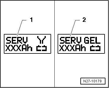
Select battery type using INFO. |
| The symbol -1- for “service
charge of wet batteries” or the symbol -2-
for “service charge of Gel/Absorbant Glass Mat (AGM) batteries”
is indicated in the display. |
| – |
Set the capacity (Ah) of the battery to be charged with the
corresponding button “Up”↑ or “Down”↓. |
| – |
Clamp the red charging clamp “+” to the positive battery
terminal. |
Note
| In the case of vehicles with a start/stop function and an
installed Battery Monitoring Control Module -J367-, the black
charging clamp “-” must be connected to the body ground. The
start/stop system will malfunction if it is connected to the
negative terminal on the battery. |
| – |
Connect the black charging clamp “-” to the negative battery
terminal. |
| The battery charger recognizes the nominal voltage of the
connected battery (6 V, 12 V or 24 V) and begins the charging
process automatically. |
|
|
|
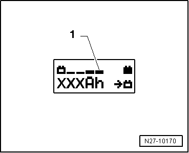
| At a charge condition of approximately 80 - 85% of the
battery voltage, charging unit begins the “Final-charging”. The
fourth bar is indicated on the display -1-.
The battery is now ready to be used. |
Note
| A successful “service charge” depends on the degree of
sulfation on the battery. |
| Possible malfunctions and how they are handled: |
| 1 - |
Displayed voltage does not match the nominal voltage: |
| – |
Hold the appropriate button “Up”↑
or “Down”↓ until the charging process
begins. |
| 2 - |
Displayed battery voltage does not match the nominal voltage
- the charging process has already begun: |
| – |
Press START/STOP twice. |
| – |
Hold the appropriate button “Up”↑
or “Down”↓ until the charging process
begins. |
| 3 - |
The charger does not recognize a battery, when the battery
voltage is less than 2 V: |
| The display remains unchanged. |
| The set operating mode and Ampere-hours (Ah) are displayed. |
| End Battery Charging Process |
| – |
Remove the black charging clamp “-” of the charger from the
negative battery terminal. |
| – |
Remove the red charging clamp “+” of the charger from the
positive battery terminal. |
| – |
Pull out the electrical system connector of the charger. |
|
|
|
Special tools and workshop equipment
required
Battery Charger -VAS5900-
WARNING
...
Special tools and workshop equipment
required
Battery Charger -VAS5900-
WARNING
...
Other materials:
Types of Batteries
General Information
Caution
The following batteries described are
maintenance-free batteries. Do not remove any of the
labels on the battery and do not add distilled water.
Only perfo ...
Changing gear using Tiptronic
Fig. 113 Selector lever in Tiptronic position
(left-hand drive) The controls are mirrored for right-hand drive vehicles
Fig. 114 Steering wheel with paddles for
Tiptronic
First read and observe the introductory information
and safety warnings Using Tiptronic, the gears can be shifted
u ...
Switching lights on and off
Fig. 68 Next to the steering wheel: examples
of the various light switches
First read and observe the introductory information
and safety warnings
Observe any country-specific regulations when using vehicle lighting.
In vehicles with a factory-fitted towing bracket, the vehicle's
rear fog ...
© 2016-2026 Copyright www.vwpolo.net

 Battery, Charging with Battery Charger -VAS5900-
 Severely Discharged Batteries, Charging with Battery Charger -VAS5900