Volkswagen Polo Service & Repair Manual: Tire Pressure Monitoring Sensor without Valve, Removing and Installing,
Vehicle Before Customer Delivery
| Special tools and workshop equipment
required |
| – |
Remove the tire from the disc wheel. |
|
|
|
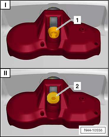
| See which version is installed before starting any work. |
| The tire pressure monitoring sensor is attached to the valve
with an inner TORX screw -1- on the
Service version. |
| If the service version is installed, the following repair
procedure must be used. Refer to
→ Anchor. |
| II - Vehicles Before Customer Delivery |
| The tire pressure monitoring sensor is attached to the valve
with a square screw with a flat head -2-
on vehicles before customer delivery. |
| If the production version is installed, the following repair
procedure must be used. Refer to
→ Anchor. |
|
|
|
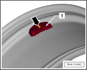
| – |
Press the tire pressure monitoring sensor
-1- onto the disk wheel (rim) and
tighten the new screw -arrow-. |
| – |
Counterhold metal valve using retainer (for example 2 mm
spiral bore) while doing so. |
 Note Note
| Visually check the valve after installing it and make sure
it is tight. The tire pressure monitoring sensor
-1- must not have any play when it
is installed and it must touch the supports in the rim bed. |
| Do not tighten the valve again to the tightening
specification after it has been installed. |
| Tightening Specifications |
| Refer to
→ Chapter „Overview - Tire Pressure Monitoring Sensor without
Valve“ |
|
|
|
Special tools and workshop equipment
required
Torque Wrench -VAG1410-
Perform the Following:
Remo ...
Special tools and workshop equipment
required
Torque Wrench 1410 -VAG1410- and Torque Wrench 1331 5-50Nm
-VAG1331-
...
Other materials:
Warning lamp
Fig. 44 Warning lamp in the instrument
cluster
First read and observe the introductory information
and safety warnings
Lights up or flashes
Possible cause
Solution
The driver seat belt and, if the front passenger seat
is occupied, the fr ...
Filling the tank with petrol or diesel
Fig. 130 In the right-hand side of the
vehicle at the rear: tank flap open
Fig. 131 Open tank flap with tank cap attached
to the holder
First read and observe the introductory information
and safety warnings Switch off the engine, ignition and the
mobile telephone before filling the ta ...
Flushing Circuit Block Diagrams
Note
The arrows in the following illustrations show the direction
of refrigerant flow while flushing. During flushing, refrigerant
flows in the opposite direction than during A/C system
operation, therefore the high pressure side of A/C se ...
© 2016-2024 Copyright www.vwpolo.net

 Caution
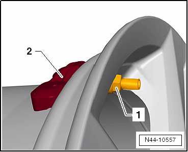
 Tire Pressure Monitoring Sensor without Metal Valve, Removing and
Installing, Service Version
Tire Pressure Monitoring Sensor without Metal Valve, Removing and
Installing, Service Version Tire Pressure Sensor and Metal Valve, Removing and Installing