Volkswagen Polo Service & Repair Manual: Overview - Wheel, RAX
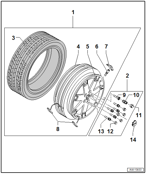
| Installing the wheel. Refer to
→ Chapter „Wheel, Mounting“. |
| There are different versions. Refer to
→ Chapter „Wheel Bolts“. |
| Side Wall Lettering. Refer to
→ Chapter „Run-Flat Tire (PAX), Lettering On Side Wall“. |
| Note assembly instructions. Refer to
→ Chapter „Tires, Mounting“. |
| Refer to the Parts Catalog for the allocation of the only valves to
be installed. |
| Batteries must be completely replaced. |
| Remaining battery life, temperature and pressure can be read via
diagnosis with Vehicle Diagnostic Tester. |
| Beru wheel electronics system. Refer to
→ Chapter „Beru Wheel Electronics Tire Pressure Monitoring Sensor,
Removing and Installing,“. |
| Siemens wheel electronics system. Refer to
→ Chapter „Siemens Wheel Electronics Tire Pressure Monitoring Sensor,
Removing and Installing“. |
| 8 - |
Adhesive Balancing Weights |
| Maximum 60 grams per rim permitted |
| Clean wheel where it will be adhered so it is free of dirt and
grease |
| Attach balance weights to intended surfaces. |
| 9 - |
Anti-Theft Wheel Bolts |
| Note assembly instructions. Refer to
→ Chapter „Wheel Bolts“. |
| Operating. Refer to
→ Fig. „“Anti-Theft Wheel Bolts”“ |
| 10 - |
Adapter for the Anti-Theft Lockable Wheel Bolt |
| Place on wheel bolt. Refer to
→ Fig. „“Anti-Theft Wheel Bolts”“ |
| 11 - |
Anti-Theft Wheel Bolt Cap |
 Note
Note
| Make sure the correct wheel bolts are installed. Refer to the Parts
Catalog. |
| Note assembly instructions. Refer to
→ Chapter „Wheel Bolts“. |
| Removing and Installing. Refer to
→ Chapter „Hub Cap for Alloy Wheels with Open Threaded Connection,
Removing and Installing“. |
1 -
Wheel
Installing the wheel. Refer to
→ Chapter „Wheel, Mounting“.
2 -
Wheel Bolts
There a ...
Other materials:
Aqua Premium System
Definition:
Water-Based Solid Mixed Paint -LWM 083 ...-
Water-Based Metallic/Pearl Effect/Special Effect Mixed Paint
-LWM 084/ 086...-
Water-Based Solid Base Paint -LWG 055 ...-
...
Overview - Tire Pressure Monitoring Sensor without Valve
1 -
Valve Cap
2 -
Nut
Individual component of -item 7-
→ Item
Tightening specification. Refer to
→ Anchor.
Always replace if removed
3 -
W ...
Safety Precautions
Safety Precautions when Painting Vehicles with Electric Drive
Caution
Risk of damaging the battery cells at too high of
drying temperatures!
Observe the maximum drying time of 30 m ...
© 2016-2026 Copyright www.vwpolo.net


 Overview - Wheel, Standard
 Tires, Mounting