Volkswagen Polo Service & Repair Manual: Checking with Restrictor, Reservoir and A/C Compressor Regulator Valve
-N280-, Externally Regulated A/C Compressor
 Note Note
| Connecting service station. Refer to
→ Chapter ‚ÄûConnecting Service Station‚Äú. |
| Observe test requirements. Refer to
→ Chapter ‚ÄûPressures, Checking‚Äú. |
| – |
Bring engine speed up to 2000 RPM. |
| – |
Pay attention to the A/C service station pressure gauge. |
Note
| Switching pressures for actuation of A/C Compressor
Regulator Valve -N280- and Coolant Fan -V7- are
vehicle-specific. |
| Increasing from initial pressure (when connecting pressure
gauges) to 20 bar (290 psi). |
|
|
|
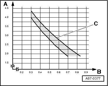
| Decreasing from initial pressure (when connecting pressure
gauges) to the value in the graph. |
| A - |
Low pressure (measured at service connection) in bar (psi)
absolute |
| B - |
Control current for A/C Compressor Regulator Valve -N280-. |
| C - |
Permissible tolerance range |
Note
| Under unfavorable conditions (very high ambient
temperatures, high humidity), pressure on high-pressure side may
increase to max. 29 bar (421 psi).
|
| The control current -B- is
shown in the measured value block. |
| The high pressure is shown in the measured value block.
Refer to
→ Rep. Gr.87. |
| Low pressure settles as a function of control current for
A/C Compressor Regulator Valve -N280- within compressor output
range in tolerance range. |
| Under unfavorable conditions (very high ambient
temperatures, high humidity), compressor output may not always
be sufficient to attain the specified value. |
| The specified operating current for the regulator valve must
be greater than 0.3 A in order to ensure reliable valve
activation. |
| In the setting “maximum cooling output” control current is
regulated to approximately 0.8 A (displayed in measured value
block). Refer to
→ Rep. Gr.87. |
| At absolute pressure, 0 bar/psi corresponds to absolute
vacuum. Normal ambient pressure corresponds to 1 bar (14.5 psi)
absolute pressure. 0 bar/psi pressure corresponds to an absolute
pressure of 1 bar (14.5 psi) on most pressure gauges (indicated
by 1 bar (14.5 psi) below 0 bar/psi). |
|
|
|
|
Possible deviation from specification |
Possible cause of fault |
Corrective
action |
| High pressure remains constant or increases only slightly
(above pressure with engine stopped), |
| Low pressure quickly drops to value in graph or below
|
| Required cooling output is not attained |
|
| Activation of A/C Compressor Regulator Valve -N280- is
faulty. |
| Not enough refrigerant in refrigerant circuit |
|
| – |
Check activation of A/C Compressor Regulator Valve -N280-.
|
| – |
Localize the leak with leak detector and eliminate |
| – |
Charge the refrigerant circuit. |
|
| Low pressure in line with value in graph |
| Required cooling output is not attained |
|
|
|
| Low pressure too low (see graph) |
| Required cooling output is not attained |
| Low pressure too low (see graph) |
| Required cooling output is not attained |
|
|
|
Note
| If no malfunction is found with this complaint, flush
(clean) refrigerant circuit with refrigerant R134a. Refer to
→ Chapter ‚ÄûRefrigerant Circuit, Flushing (Cleaning) with
Refrigerant R134a“. If that is not possible in this
workshop, flush the refrigerant circuit with compressed air and
remove moisture with nitrogen. Refer to
→ Chapter ‚ÄûRefrigerant Circuit, Flushing with Compressed Air and
Nitrogen“. |
|
|
|
|
Possible deviation from specification |
Possible cause of fault |
Corrective
action |
| High pressure only increases slightly above pressure with
engine stopped |
| Low pressure drops only slightly |
| Required cooling output is not attained |
|
| Activation of A/C Compressor Regulator Valve -N280- is
faulty. |
|
| – |
Check activation of A/C Compressor Regulator Valve -N280-. |
| – |
Flush (clean) refrigerant circuit. Refer to
→ Chapter ‚ÄûRefrigerant Circuit, Flushing (Cleaning) with
Refrigerant R134a“. |
| – |
Replace A/C compressor. |
|
| High pressure increases above specification |
| Low pressure drops only slightly |
| Required cooling output is not attained |
|
| Constriction or obstruction in refrigerant circuit |
|
| – |
Run hand over refrigerant circuit to check for differences
in temperature |
| If difference in temperature is found at one component: |
| – |
Replace the hose or pipe if kinked or constricted. |
| – |
In the event of an obstruction, flush refrigerant circuit
with compressed air and nitrogen |
| If no malfunction can be found: |
| – |
Flush (clean) refrigerant circuit. Refer to
→ Chapter ‚ÄûRefrigerant Circuit, Flushing (Cleaning) with
Refrigerant R134a“. |
|
| High and low pressure normal at first, after some time high
pressure increases above specification |
| Low pressure quickly drops to value in graph or below, |
| Required cooling output is no longer attained. |
|
| Moisture in refrigerant circuit |
|
| – |
Flush refrigerant circuit with compressed air and nitrogen. |
| – |
Repeat test if function is not OK. |
| – |
Flush (clean) refrigerant circuit. Refer to
→ Chapter ‚ÄûRefrigerant Circuit, Flushing (Cleaning) with
Refrigerant R134a“. |
| – |
Charge the refrigerant circuit. |
|
| Low pressure too low (see graph) |
| The required cooling performance is obtained |
|
| Activation of A/C Compressor Regulator Valve -N280- is
faulty. |
|
| – |
Check activation of A/C Compressor Regulator Valve -N280-. |
| – |
Flush (clean) refrigerant circuit. Refer to
→ Chapter ‚ÄûRefrigerant Circuit, Flushing (Cleaning) with
Refrigerant R134a“. |
| – |
Replace A/C compressor.
|
|
Note
| For the malfunction “high pressure normal, low pressure too
low”, note the following: faulty, the evaporator can ice up or
the cooling output is not reached. |
| With this malfunction, evaporator may ice up although
quantity of refrigerant in circuit is OK. |
| Check measured values of Evaporator Vent Temperature Sensor
-G263- or Evaporator Temperature Sensor -G308-. |
| Check the A/C Compressor Regulator Valve -N280- activation. |
|
|
|
|
Possible deviation from specification |
Possible cause of fault |
Corrective
action |
| High pressure normal or too high |
| Low pressure too high (see graph) |
| A/C compressor noise (particularly after switch-on) |
| Required cooling output is not attained |
|
| Too much refrigerant in the circuit. |
|
| – |
Extract refrigerant from the refrigerant circuit |
| If quantity of refrigerant extracted roughly corresponds to
specified capacity: |
| – |
Replace the A/C compressor. |
| If quantity of refrigerant extracted is substantially
greater than specified capacity: |
| – |
Charge the refrigerant circuit. |
|
| High and low pressure normal |
| Required cooling output is not attained |
|
| To much refrigerant oil in the circuit. |
|
| – |
Discharge the refrigerant circuit. |
| – |
Flush (clean) refrigerant circuit. Refer to
→ Chapter ‚ÄûRefrigerant Circuit, Flushing (Cleaning) with
Refrigerant R134a“. |
|
| High and low pressure normal |
| A/C compressor noise (particularly after switch-on) |
| The required cooling performance is obtained |
|
|
|
Note
| Overfilling with refrigerant oil can occur if, for example, the
compressor has been replaced without adjusting the quantity of
refrigerant oil. |
| If the A/C compressor is not replaced, the refrigerant oil should be
drained from the A/C compressor via the oil drain plug. Out of the
entire quantity of refrigerant oil, 50 grams should be put in the A/C
compressor and the rest in the refrigerant circuit. Refer to
vehicle-specific repair manual. |
–
Turn off the ignition.
–
Connect pressure gauge battery (A/C service station).
–
Take pr ...
Specified Values
Note
Connecting service station. Refer to
→ Chapter ‚ÄûConnecting Service Station‚ ...
Other materials:
Switching the front passenger front airbag on and off manually using the key-operated
switch
Fig. 58 In the stowage compartment on
the front passenger side: key switch for disabling and enabling the front airbag
on the front passenger side
First read and observe the introductory information
and safety warnings
The front passenger front airbag must be switched off when securing a
...
Introduction
This chapter contains information on the following subjects:
‚Üí Operating ParkPilot ‚Äâ
‚Üí Acoustic and optical ParkPilot signals at the rear of the vehicle
The ParkPilot assists the driver when manoeuvring and parking.
The ultrasound sensors in the rear bumper transmit and recei ...
A/C Refrigerant High Pressure Switch -F23
Note
For switching pressures, removing and installing switches
and switch arrangement and version, see vehicle-specific
refrigerant circuit.
Refer to
→ Rep. Gr.87.
...
© 2016-2025 Copyright www.vwpolo.net

 Checking
 Checking with Expansion Valve, Receiver/Dryer and A/C Compressor Regulator
Valve -N280-, Externally Regulated A/C Compressor
Checking with Expansion Valve, Receiver/Dryer and A/C Compressor Regulator
Valve -N280-, Externally Regulated A/C Compressor